
Table of contents
(The feature image credits: Introducing the Smart Configurator Board Support Feature for Quick Project Setup - Renesas Blog.
Searched by renesas smart configurator in
DDG image
and Google lens.)
e2 Studio
Debug
References:
-
e² studio快速入门指南 (3/3) - 构建和调试RL78项目 - bilibili - 瑞萨电子
- Searched by
RL78 smart configuratorin bilibili
- Searched by
-
- Searched by
Notes:
- It’s an variant of GDB. r1-Bili
Install
References:
Notes:
-
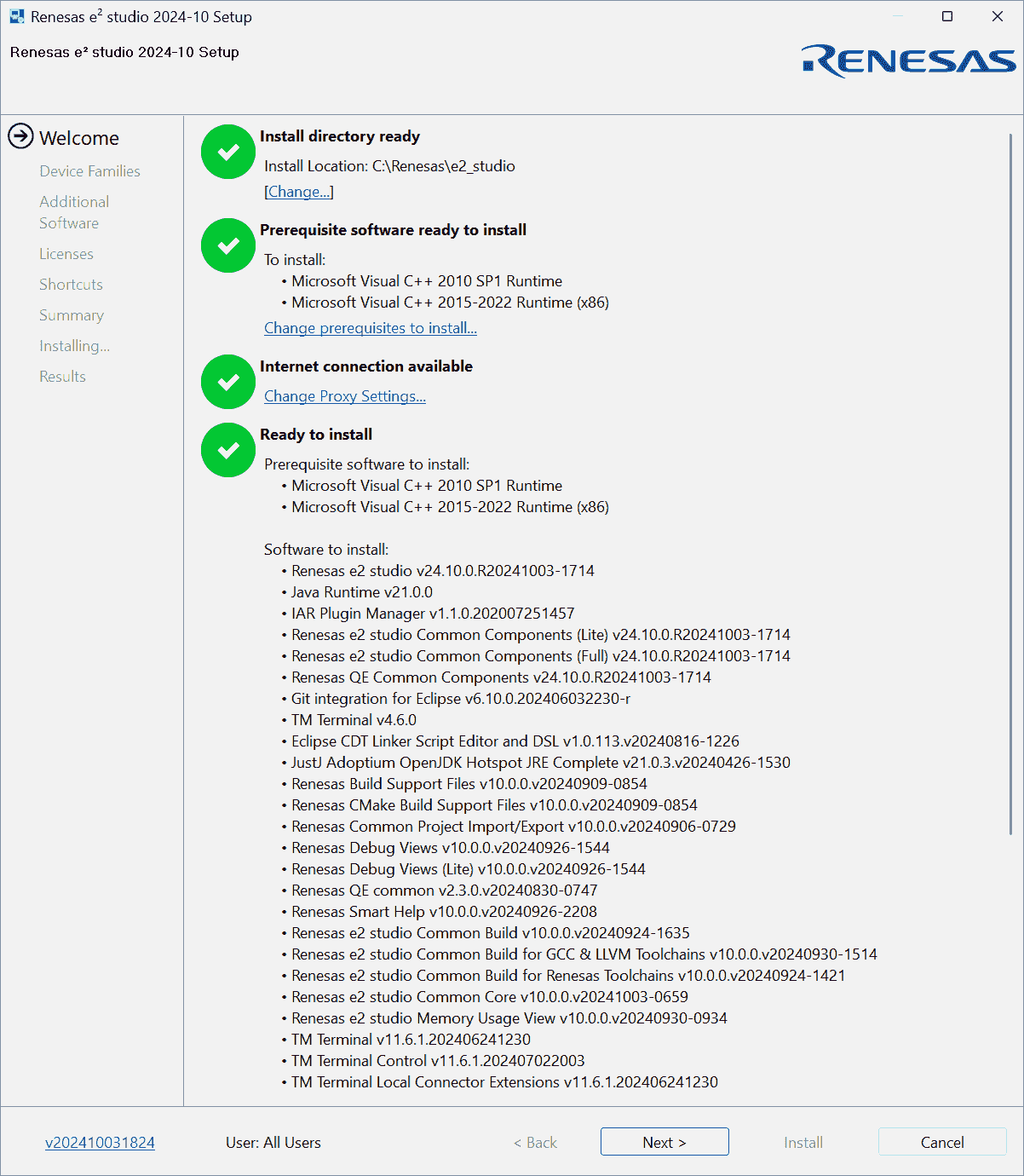
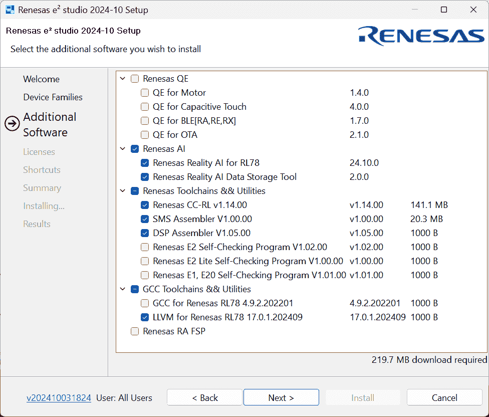
Install package: e² studio 2024-10 installer for Windows
-
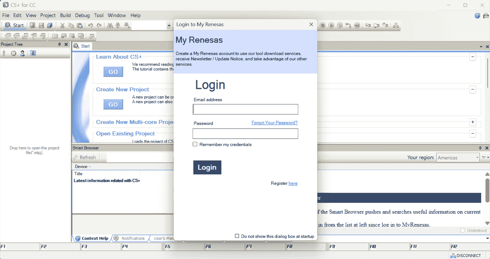
Installed CS+ for CC V8.12.00
-
Open Projects
References:
-
e2studio - Importing and Exporting an e2studio Project - YouTube - RenesasPresents
- Searched by
How to open an e2 studio projectin DDG
- Searched by
-
Importing Projects to e² studio | Renesas Customer Hub
- Searched by
import CS+ project to e2 studioin DDG
- Searched by
-
Smart Configurator , Code Generator - Renesas Electronics Corporation
- Searched by
renesas rcpc filein DDG
- Searched by
-
Porting from the e² studio to CS+ | Renesas
- Searched by
will e2 studio generate an .rcpc file automatically?in DDG
- Searched by
-
Project Conversion between e2 studio and CS+, Notes and Tips
- Searched by s4
Notes:
(2024-12-18)
-
Add a project (.zip) into the workspace r1-YouTube
Import > General > Existing Projects into Workspace > (Next) Select archive file > Finish
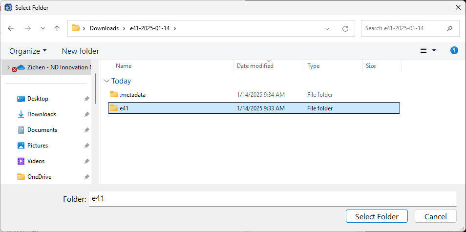
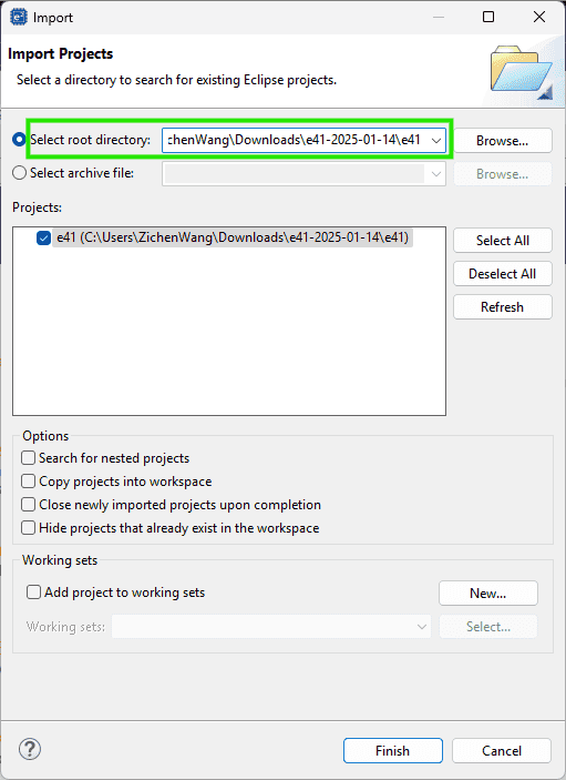
(2025-01-14)
-
Example of opening e41:
-
Import existing projects

-
-
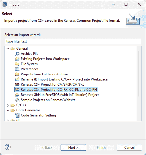
(2024-12-30)
-
Import a CS+ project into e2 studio by selecting the
.rcpefile r2-Hub: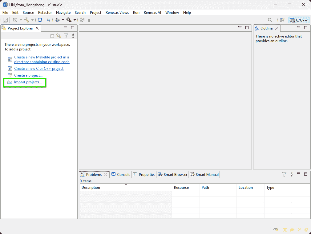
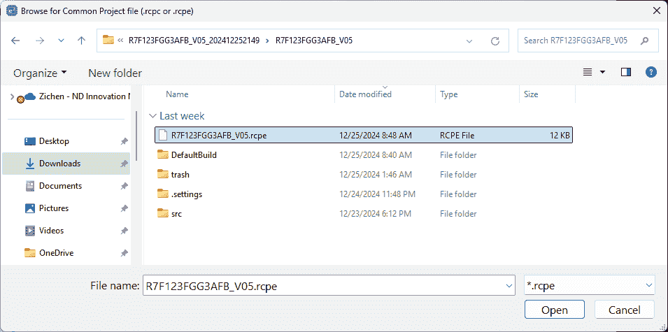
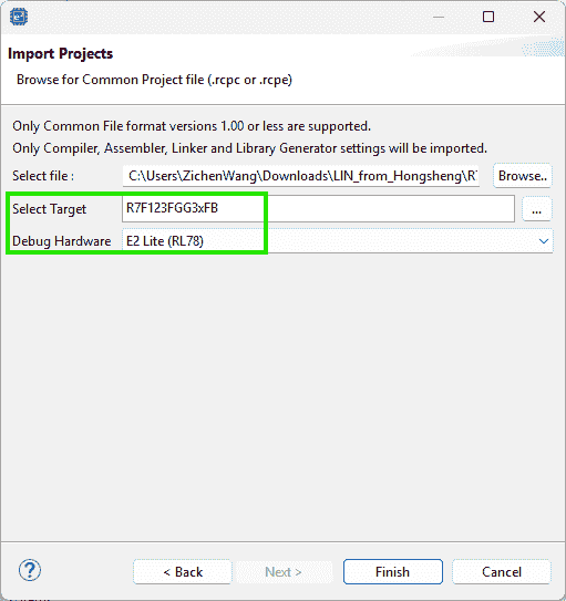
(2024-12-31)
-
.rcpcmeans “Renesas Common Project File” r3-Note-
An
.rcpccan be generated byExportthe project as aRenesas Common Project File, which can be ported to CS+. r4-Port -
Inversely, CS+ will generate an .rcpe for converting to an e2 studio project r5-Convert.
-
Smart Configurator
Symbolic Name
References:
-
RL78 Smart Configurator - Manuals+
- Searched by
RL78 Smart Configurator How to configure Pin functionsin DDG
- Searched by
-
RL78 Smart Configurator - User’s Guide: IAREW - Docs
- Found in RL78/F23 Guide for Engineer - Renesas Electronics Corporation
- Searched by
RL78/F23, F24 Setup Procedure for LIN Communication in Master Mode (Guidance)in DDG
Notes:
(2024-11-06)
-
The “Symbolic Name” attribute of pins will show up by clicking the “Pin Number” page
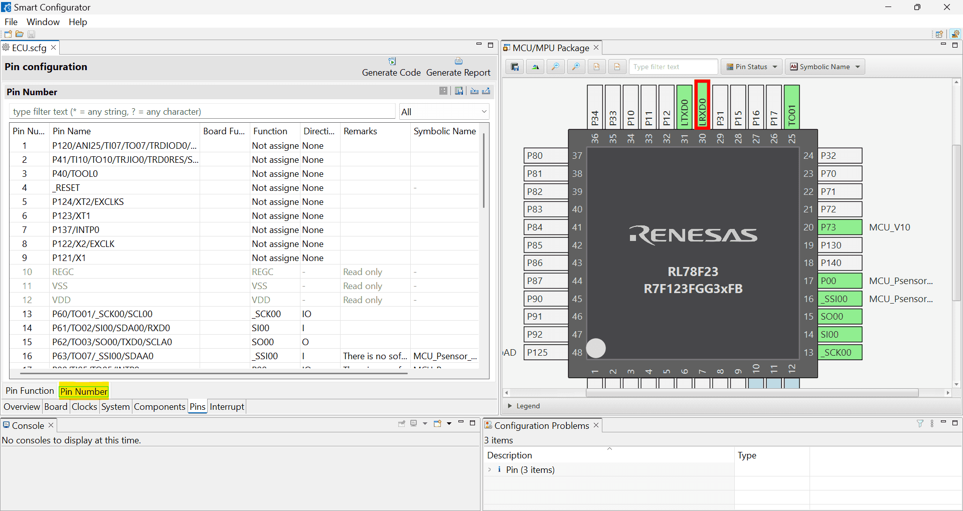
(2024-11-13)
- Use the Smart Configurator to generate code for developing in IAR r2-Docs.
CS+ for CC (RL78)
Workspace Options
References
-
【General - Text Editor】 category | CS+ V4.01.00 - tool-support.renesas.com
- Searched by
renesas CS+ editor optionsin DDG
- Searched by
Text Editor
(2025/02/21)
- Tab width: 8 -> 4
Build Process
ROM
Problem:
-
Building failed with this error:
1
2
E0562320:Section address overflowed out of range : ".monitor2" Renesas Optimizing Linker Abort
Reset to Defaults
Problem:
- I don’t know how to restore default settings after changing some options.
References:
-
CS+ V8.04.00 Integrated Development Environment User’s Manual: Project …
- Searched by
renesas CS+ reset building optionsin DDG
- Searched by
Practices:
(2025-01-10)
- Right click on the pane to open a context menu.
Generate HEX
Problems:
-
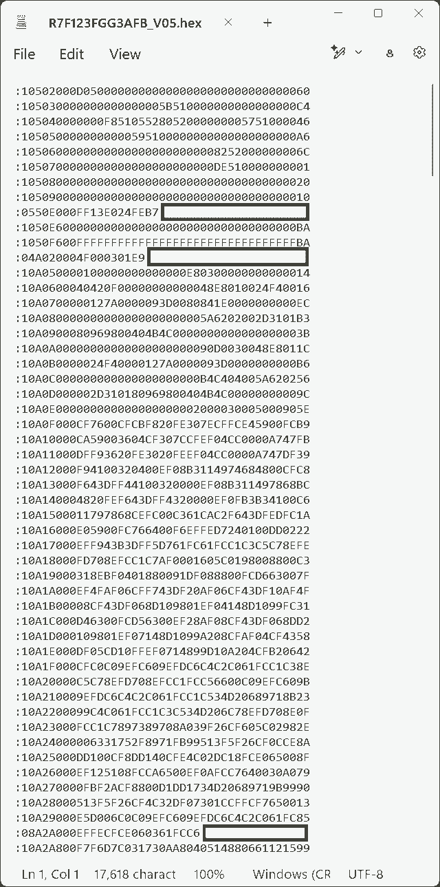
How to generate a .hex file like this image r1-Prod, each line has a fixed length.
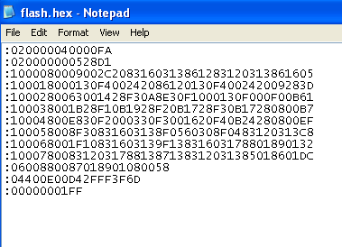
- But in the hex file generated by CS+, each line is very long.
References:
-
Understanding Hex Files - Electronic Products
- Searched by
hex file examplein Google Images
- Searched by
Practices:
(2025-01-10)
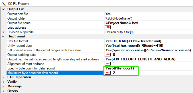
-
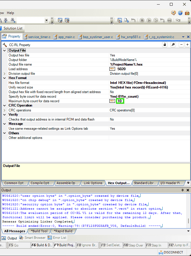
CC-RL (Build Tool) > Property > Hex Format > Maximum byte count for data record
(2025-01-14)
-
VSCode extension for .hex files:
-
Intel HEX format can update the checksum.
-
The meaning of each segment is introduced in r1-Electronic Products.
-
References
-
I am unable to resolve this error E0562320:Section address overflowed out of range : “.text” - Support Forums
- Found in the Smart Browser inside the CS+.
- Smart Browser is opened by clicking
Help for Messageafter selecting the error message.
Notes:
-
The
Propertytab of containing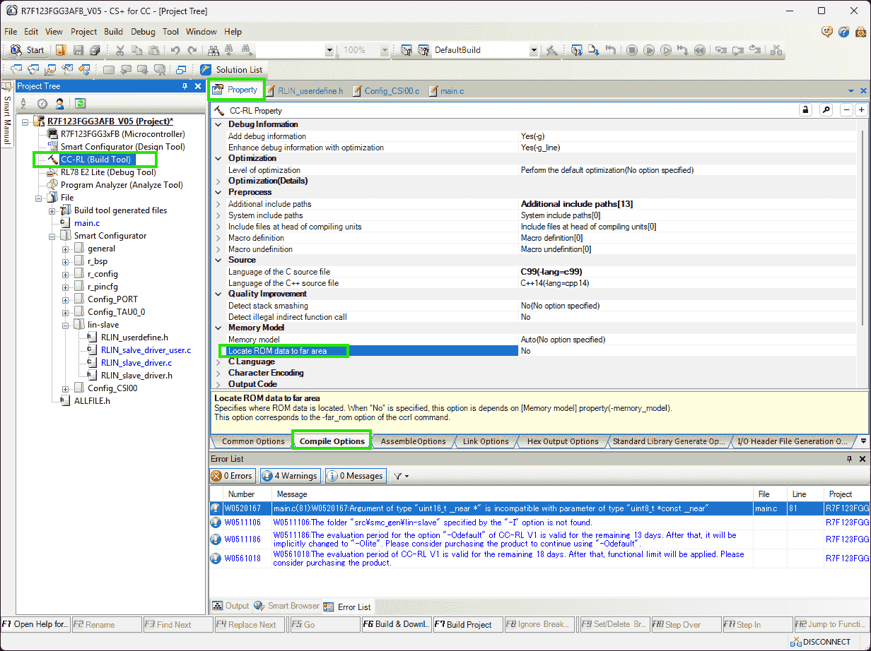
Write Flash
Problem:
(2025-01-10)
-
客户要求 hex 文件的开头是代码的描述信息,这个就需要我们在编译的时候,把描述信息也包含进来吧, 请问这个应该怎么做?是不是要设置 linker?
描述信息是一个如下所示的结构体,客户要求把这个结构体放在 hex 文件中,放在应用代码之前
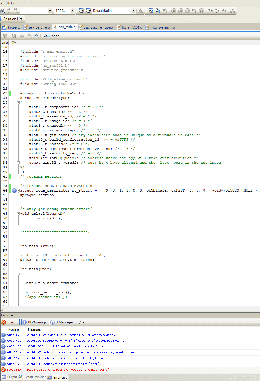
 1
 2
 3
 4
 5
 6
 7
 8
 9
10
11
12
13
14
15
16
17
struct code_descriptor { uint16_t component_id; /* = 79 */ uint8_t pcba_id; /* = 3 */ uint8_t assembly_id; /* = 1 */ uint16_t usage_id; /* = 1 */ uint8_t unused1; /* = 0 */ uint8_t firmware_type; /* = 0 */ uint64_t git_hash; /* any identifier that is unique to a firmware release */ uint16_t build_configuration_id; /* = 0xFFFF */ uint16_t unused2; /* = 0 */ uint16_t bootloader_protocol_version; /* = 5 */ uint16_t security_rev; /* = 0 */ void (*c_int00)(void); /* address where the app will take over execution */ const uint32_t *crc32; /* must be 4-byte aligned and the _last_ word in the app image */ }; -
Write a
structcontaining software information into flash memory (ROM), not RAM. -
The
structshould be the first part of the hex file. Whilememcpyis writing data into the RAM.
References:
-
Ask ChatGPT
- How to make a struct compiled first and being put at first in the hex file?
- The compiler I am using is: CC-RL. Are the steps the same?
-
CC-RL Compiler User’s Manual - Renesas Electronics Corporation
- Searched by
renesas cc-rl manualin DDG
- Searched by
- Ask ChatGPT
Practices:
(2025-01-12)
-
Use the
#pragma sectiondirective to place thestructin a named section, and modify the linker script r1-ChatGPT.-
The linker script should be the
.clnkfile, as the command in the.mapfile shows an option:-subcommand=DefaultBuild\Test_INTTM00.clnk -
Code:
 1
 2
 3
 4
 5
 6
 7
 8
 9
10
#pragma section data MySection struct MyStruct { int a; char b; }; #pragma section #pragma section data MySection struct MyStruct my_struct = { 0x1234, 'A' }; #pragma section -
Linker script:
1
2
3
4
5
6
7
8
9
SECTION ROM1 START: 0x000000 END: 0x00FFFF { .MySection .text .data ... }
-
-
Introductions on Manual r2-Manual:
- Chapter: 3.2.5 Link map information (p. 298)
-
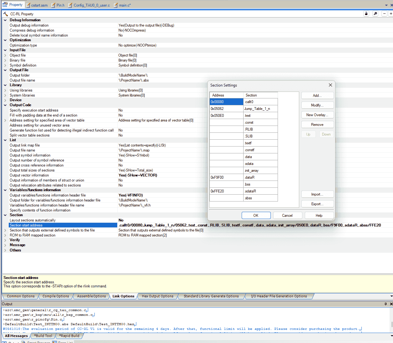
Building options can be specified through the property of
CC-RL (Build Tool)in “CS+ for CC” IDE:-
Cannot manually specify sections when the option is on:
Link Options>Section>Layout sections automatically-
I found this after I tried many time to change the
Section start address, but cannot get desired results:.vectsection isn’t allowed to be modified.MySectionis not assigned address.-
And once ChatGPT suggested turning on the “Layout automatically” temporarily
Debugging Tips
- Use the map file to confirm memory usage and section placements.
- If issues persist, temporarily enable “Layout sections automatically” to let the linker determine the layout, then analyze the resulting map file for hints.
-
-
-
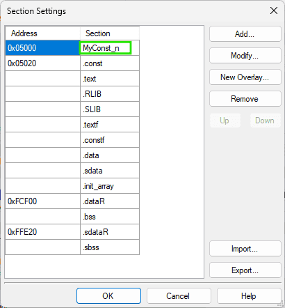
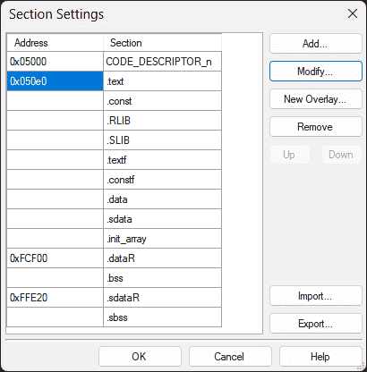
By turning off the “Layout sections automatically”, setting it to
No, TheSection start addresswill list all sections.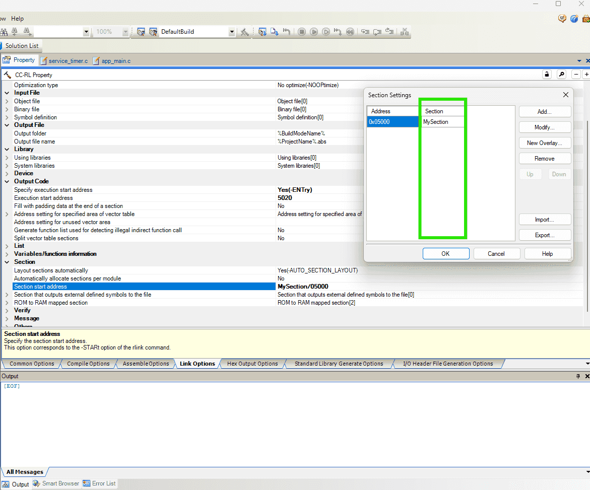
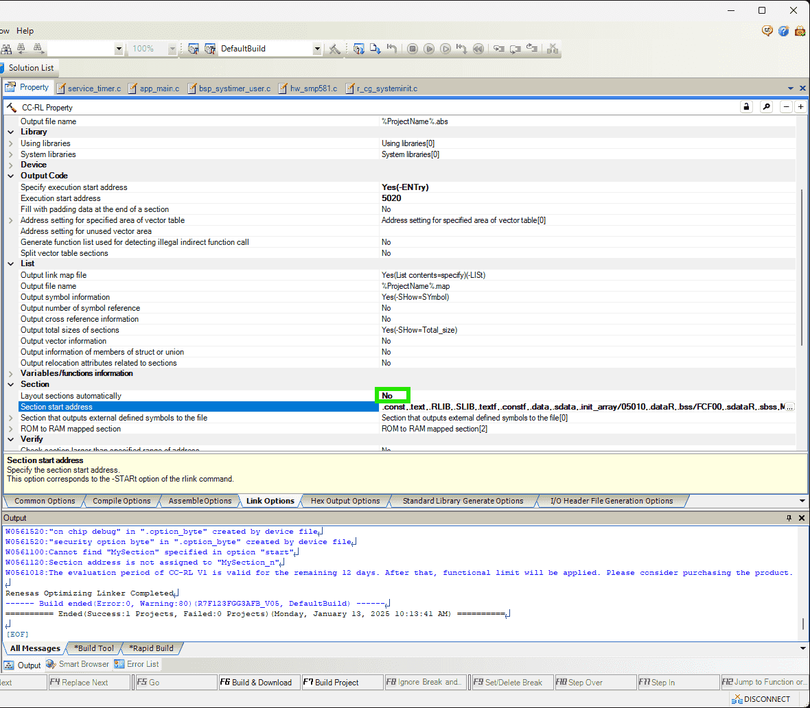
-
Also, the
Load addressinHex Output Options>Output Filehas range limitations, where it cannot be specified as an arbitrary address, such as5000(0is okay).1(E) E0562101 E0562101:Invalid address specified in option "output" : "5000" R7F123FGG3AFB_V05.mtpj
-
-
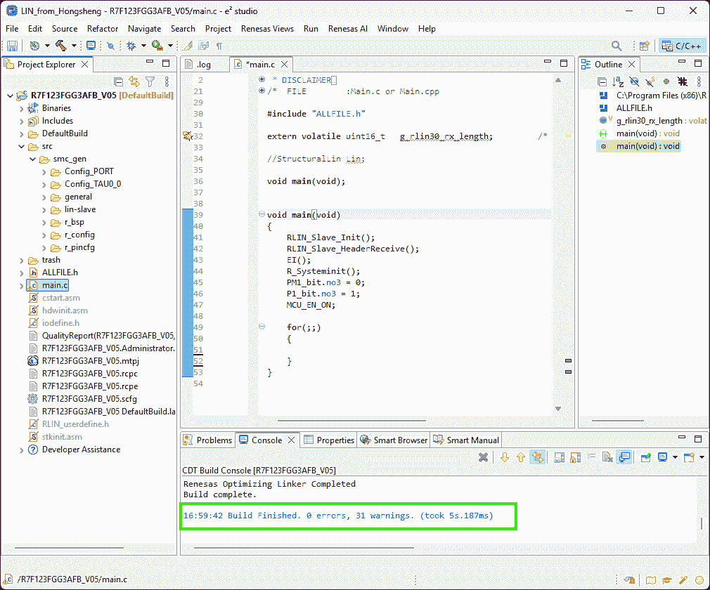
Files after building:
-
The file
QualityReport(R7F123FGG3AFB_V05,DefaultBuild).txtrecords the building information. -
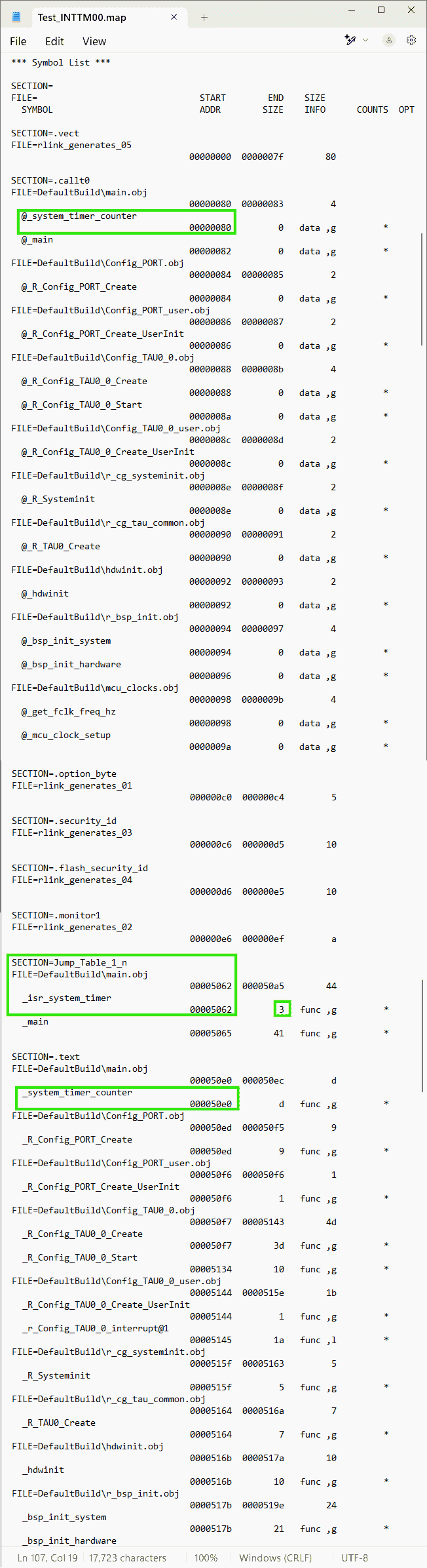
Mapping list exists in
R7F123FGG3AFB_V05.map1 2 3 4 5 6 7 8 9 10 11 12 13 14 15 16 17 18 19 20 21 22 23 24 25 26 27 28 29 30 31 32 33 34 35 36 37*** Mapping List *** SECTION START END SIZE ALIGN .vect 00000000 0000007f 80 0 .constf 00000080 00000080 0 2 .init_array 00000080 00000080 0 2 .sdata 00000080 00000080 0 2 .data 00000082 00000085 4 2 .option_byte 000000c0 000000c4 5 1 .RLIB 000000c5 000000c5 0 1 .security_id 000000c6 000000d5 10 1 .flash_security_id 000000d6 000000e5 10 1 .text 000000e6 0000029d 1b8 1 .textf 0000029e 00001165 ec8 1 .SLIB 00001166 00001889 724 1 .const 00003000 0000309f a0 2 .bss 000fcf00 000fcf77 78 2 .dataR 000fcf78 000fcf7b 4 2 .sbss 000ffe20 000ffe20 0 2 .sdataR 000ffe20 000ffe20 0 2 -
Assemble list is shown in the
app_main.prn, which is generated by checking the option:Compile Options->Assemble List->Output assemble list file-> Yes -
Building command is recorded in
R7F123FGG3AFB_V05.clnk.
-
-
The command
-lnkcmdis not allowed to be written in the filed:Link Options>Others>Other additional optionsr3-ChatGPT. -
The declared section name will be added a suffix
_n, which indicates “near” r4-Manual p.918 Quick Guide. -
The sequence of different sections in the generated .hex file ususally is (referring to the
.mapfile):-
The 4 sections
.vect,.option_byte,.security_id,.flash_security_idwill always be at the beginning of the .hex file after each time building, even though I manually specify their address in theSection start address. -
Those 4 sections are not initially listed in the option
Section start address, so I guess they cannot be changed.However, I can switch the position of
-
The flash memory left for application code ranges
0x0000to0x8000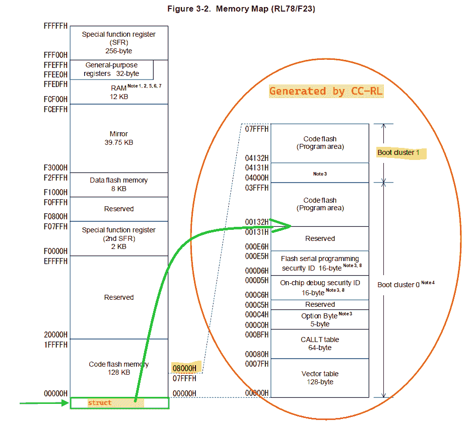
(2025-01-23)
- The code descriptor struct is required to be put at
0x5000. We don’t have access to.vectsections
- The code descriptor struct is required to be put at
-
Fred Assist
(2025-01-14)
- Define struct
Define Section
Problem:
-
Error:
References:
-
What is the use of “#pragma section
” in C? - SO -
RL78 Family One Image Bootloader RL78 One Image Bootloader Example …
- Searched by
rl78 AppStartAddrin DDG
- Searched by
Practices:
(2025-01-13)
-
GCC attribute supports
__attribute__section r1-SO. -
When you are confused, just go to debug the code or read the documents.
-
I was randomly reading the manual.
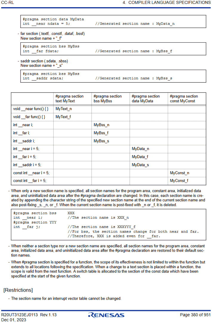
Jumping sequence: Quick Guide A.2.1 -> “Changing compiler output section name” Page 379 in Ch 4.2.4
-
I found the important table on Page 380. which indicates that different types of variables will be assigned to different sections. And finally understanded the explanation about the format rule of section names on Page 379.
-
I tried to test a simple case, an integer:
1 2#pragma section const MyConst const uint16_t __near component_id = 79;And I also tried to use the section name
MyConst_nwith suffix added as demonstrated in the example, and also shown in the generated.mapfile. It works.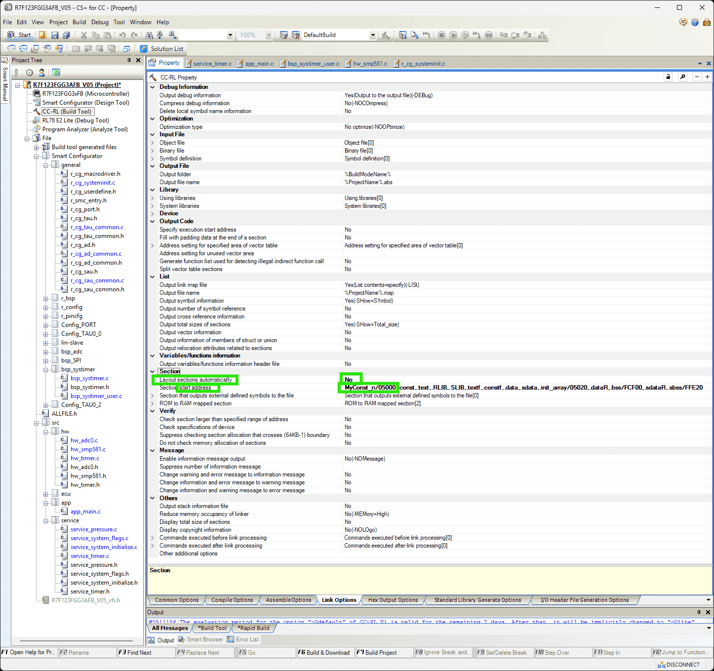
-
(2025-01-15)
- Constant data cannot exist before address 0x3000 r2-Manual.
Padding
Problems:
-
The customer’s SDP requires each line in the hex file to be the same length. But the lines in generated hex file have various length.
How to padd each line to the same length?
Notes:
(2025-01-14)
- The hex file needs to be continuous, as the memory needs to be filled seamlessly, instead of only including the sections occupied by code.
(2025-01-16)
-
Ensure the Start address is the
textsection (for code). It’s better to delete the .hex file before rebuilding it, because the settings of CS+ may not be kept when packaging the project into a .zip file.
Vect
Problem:
- Need to use the vector table stored in the customer’s bootloader program.
References:
- -VECT | CS+ V6.00.00
- CC-RL Compiler User’s Manual, RL78 Family, Rev 1.13
-
RL78 Bootloader Jump to App Issue
- Searched by
jmp asm code for rl78in Google
- Searched by
-
RL78 Dual Image Bootloader Example - Application Project
- Searched by
RL78 Bootloader Jump to App Issuein DDG
- Searched by
-
Are there any examples how to define ISR vectors?
- Searched by
renesas rl78 isr handlerin DDG
- Searched by
Practices:
(2025-01-14)
-
The
-vectoptions r1-Docs can be added in the compiling command in theOther additional optionsfield.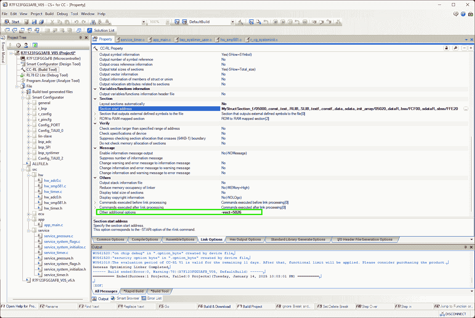
- Add
-show=vectorin command to print “Variable Vector Table List” in the.mapfile r2-Manual P.304
(2025-02-19)
-
I think the text Boyd sent on Jan 14 was copied out from the linker script of the boot project developed on his side.
1 2 3 4 5 6 7 8 9 10 11 12 13 14 15 16 17 18 19 20 21 22 23 24 25 26 27 28 29 30 31 32 33 34 35 36 37 38 39 40 41 42 43 44 45 46 47 48 49 50 51 52 53 54 55 56 57 58 59 60 61 62-VECTN=4=5026 -VECTN=6=5029 -VECTN=8=502C -VECTN=A=502F -VECTN=C=5032 -VECTN=E=5035 -VECTN=10=5038 -VECTN=12=503B -VECTN=14=503E -VECTN=16=5041 -VECTN=18=5044 -VECTN=1A=5047 -VECTN=1C=504A -VECTN=1E=504D -VECTN=20=5050 -VECTN=22=5053 -VECTN=24=5056 -VECTN=26=5059 -VECTN=28=505C -VECTN=2A=505F -VECTN=2C=5062 -VECTN=2E=5065 -VECTN=30=5068 -VECTN=32=506B -VECTN=34=506E -VECTN=36=5071 -VECTN=38=5074 -VECTN=3A=5077 -VECTN=3C=507A -VECTN=3E=507D -VECTN=40=5080 -VECTN=42=5083 -VECTN=44=5086 -VECTN=46=5089 -VECTN=48=508C -VECTN=4A=508F -VECTN=4C=5092 -VECTN=4E=5095 -VECTN=50=5098 -VECTN=52=509B -VECTN=54=509E -VECTN=56=50A1 -VECTN=58=50A4 -VECTN=5A=50A7 -VECTN=5C=50AA -VECTN=5E=50AD -VECTN=60=50B0 -VECTN=62=50B3 -VECTN=64=50B6 -VECTN=66=50B9 -VECTN=68=50BC -VECTN=6A=50BF -VECTN=6C=50C2 -VECTN=6E=50C5 -VECTN=70=50C8 -VECTN=72=50CB -VECTN=74=50CE -VECTN=76=50D1 -VECTN=78=50D4 -VECTN=7A=50D7 -VECTN=7C=50DA -VECTN=7E=50DD- The “vector number” has an interval of 2 bytes, whereas
each entry in the jump table is of 3 bytes, as
they are a
BR !_funcinstruction, whose Op code and Oprand take 3 bytes in total, e.g.,ED5766
- The “vector number” has an interval of 2 bytes, whereas
each entry in the jump table is of 3 bytes, as
they are a
- Add
(2025-01-15)
-
The vector table area range (from 0x00 -> 0x7F) belongs to the vector table of the bootloader program controlled by the customer r3-Forums.
I cannot use the customer’s vector table, so I have to implement a jump table.
-
The jump table is an array of function pointers to the ISR handlers r4-Example, r5-Question.
(2025-01-20)
-
-split_vectwill create sections according to “vector table address” r2-Manual P.201 (Noticed this option when looking through CS+ CC-RL property)-
By adding this option, the “Vector Table Address” can be observed in the “Mapping List” of the .map file:
SECTION START END SIZE ALIGN .vect0 0x00 0x01 2 0 .vect2 0x02 0x03 2 0 .vect44 0x2c 0x2d 2 0 .data 0x74 0x77 4 2 As shown in the above list, the address of vect44 is
0x2C, which is exactly theINTTM00interrupt.0x2Cis the address of vector #20 both in the vector table and the flash memory in a normal project (as shown in the following image).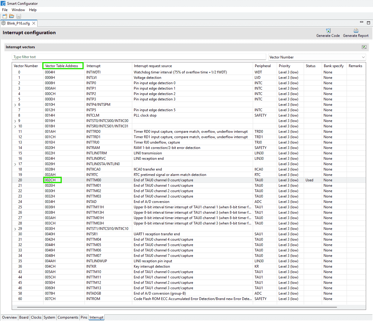
-
-
Unused area in a vector table can be assigned with address with
-vectn, which can be configured in the option:Address setting for specified area of vector table -
However,
-vectn=2C=5062cannot change the default address5080stored in the vector table, maybe due to the priority: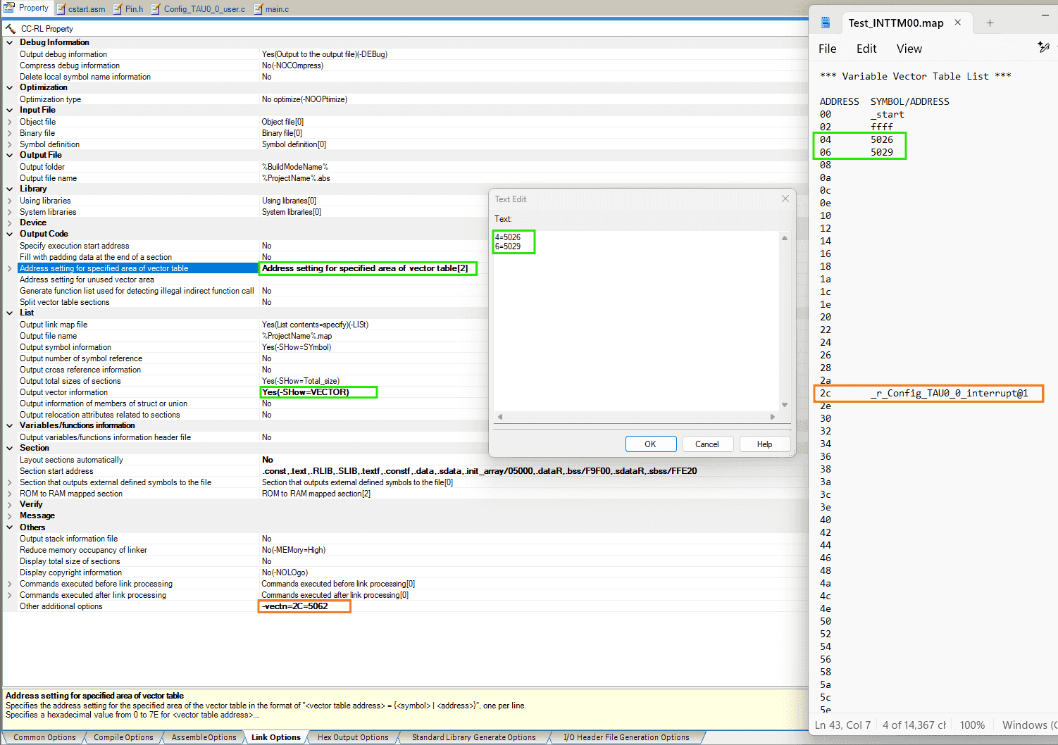
-
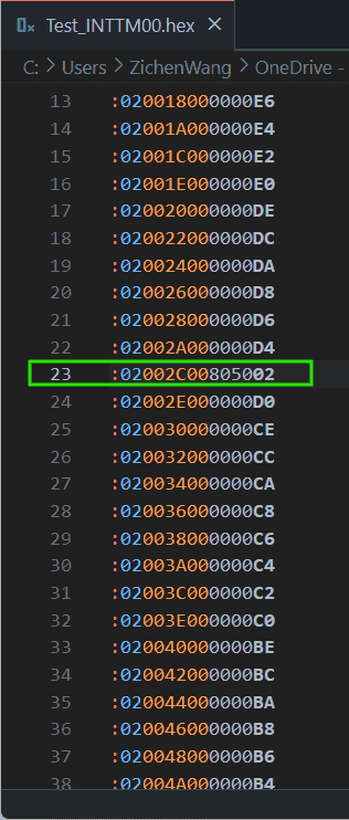
By setting the output hex file format to two bytes per line, it’s easier to check the vector table:
-
The
0x5080is the address of the interrupt function:r_Config_TAU0_0_interrupt, whose corresponding symbol is: “the external name of the target function prefixed with an underscore (_)” r2-Manual p.199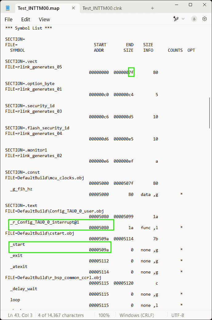
Therefore, I need the address
0x5080(inside the cell whose address in the vector table is0x2C, i.e., the 44-th byte in the vector table, corresponding to the vector number is #22) to be0x5062. -
But, I suspect that I have no access to the function
r_Config_TAU0_0_interruptat all, so I need to jump to my customized function.That is why there should be a jmp command at
0x5062.Considering to add a snippet of assemble code r2-Manual p.389:
1#pragma inline_asm -
I wonder if I can use
callinstead ofjmp. And then I found#pragma calltdown below in the Docs.
-
Callt
References:
-
RL78 Family C compiler CC-RL Programming Techniques - Rev.1.10
- Searched by
rl78 callt usagein DDG
- Searched by
- CC-RL Compiler User’s Manual, RL78 Family, Rev 1.13
(2025-01-20)
-
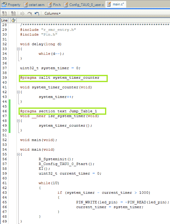
#pragma calltwill notify the compiler that the function will be called bycalltinstruction. It’s similar to:#pragma interrupt r_Config_TAU0_0_interrupt(vect=INTTM00), which notifies the compiler that it’s a hardware interrupt handler.-
The callt instruction table is:
0x80-0xBFafter the vector table (0x00-0x7F) r2-Manual p.395. -
Boyd also mentioned
calltin his email. -
And the
callinstruction is of 2 bytes, satisfying the requires of 3-byte long command.
-
-
__calltand#pragma callthave similar effect r1-Tech.1 2 3 4 5 6 7 8 9 10 11#pragma callt func1 void func1(void) { system_timer++; } void main (void) { func1(); } -
The section
.callt0is not configured when not using “Layout Automatically”, so I need to create it manually. And the memory has to be 0x80-0xBF. Otherwise, without satisfying the above 2 conditions, there will be an error:(E) E0562320 E0562320:Section address overflowed out of range : ".callt0"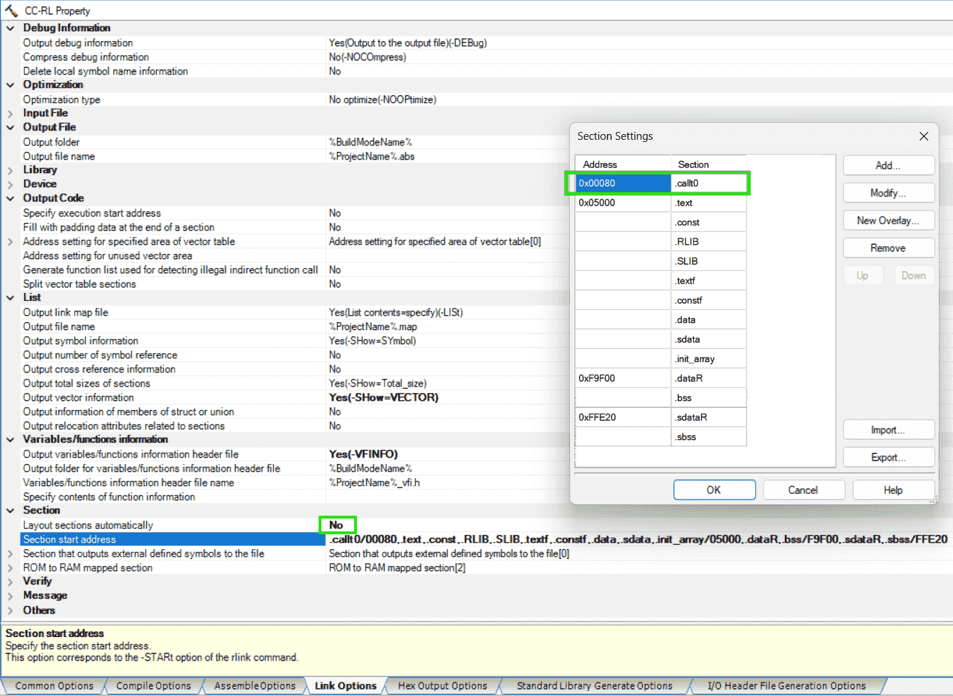
-
I guess that the function (name) to be called by the
calltinstruction cannot be relocated, as they’re recorded in the “callt instruction table”, stored in the area: 0x80 - 0xBF -
According to the customer’s instruction below, I think I should: Put “function calling” (based on callt instruction) at the specified address. Such that, when an interrupt is triggered, the program will jump to corresponding address. For example, I put
func1();at0x5026. Then, when the interrupt whose address in the vector table is0x4is enabled, the program will jump to0x5026Allocate 0x5026-0x50E0 for a “vector table”. Interrupts will jump to locations in this table. To find the address (A) of an interrupt (N) use the formula: A = 0x5026 + 0x3 * ((N / 0x2) - 0x2). Or use the table below. The address should contain the instruction “CALL isr_function” (please verify this instruction is 3 bytes long).
Interrupt (N) Address (A) 0x4 0x5026 0x6 0x5029 0x8 0x502C 0xA 0x502F 0xC 0x5032 0xE 0x5035 0x10 0x5038 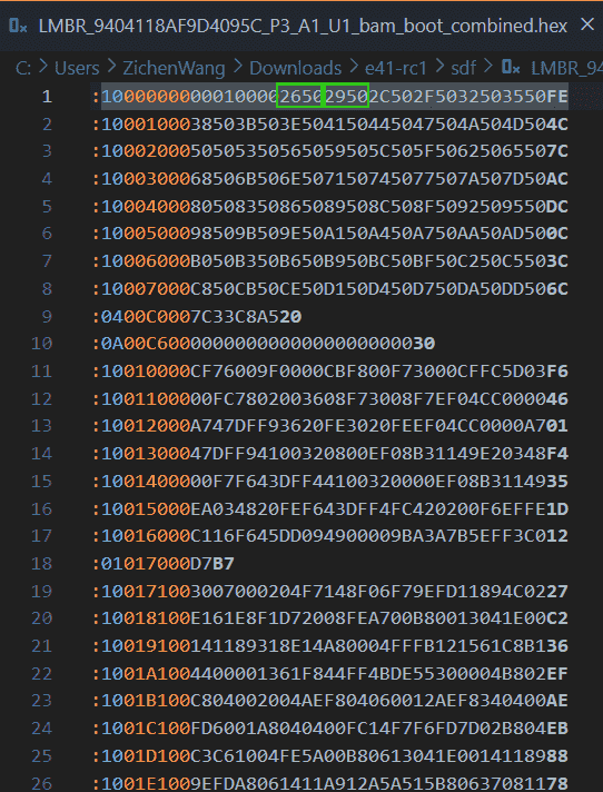
Jump Table
Problem:
- After definition, how to link the jump table?
References:
- RL78 Dual Image Bootloader Example - Application Project
-
RL78/F23, F24 Interrupt Source Determination
- Searched by
f23 interrupt address listin DDG
- Searched by
Notes:
(2025-01-16)
-
Initialized vector table > Initialized Interrupt function > Jump table > ISR Handler > ISR r1-Manual p.8.
-
The initial vector table contains 16-bit length address, ranging from 0x0000 ~ 0xFFFF
-
Jump table is at the beginning of each application.
-
“Handler” means function name
-
Jump table contains 4-byte address, which are pointers to the function name
- An entry of jump table:
-
The initial (the normal situation, generated by Smart Configurator) ISR will need to implement a
JMPfunction. -
The address of the ISR Handler may change every compiling, the the boot knows can found its address in the cell of the Jump table, as the jump table is put at a fixed position: the beginning of application region.
So the initialized Interrupt function: ISRx_vte() should do something
write ato go to the cell of the jump table, to get the address of the ISR Handler.JMP -
The address to the ISR Handler can
-
Timer ISR
Problem:
(2025-01-16)
- Duplicate the example code in CS+ to evaluate an interval timer interrupt
(2025-01-26)
-
The vector table (0x00 - 0x7F) specifies the address to be jumpped.
- The
0x51FBis the address of the interrupt function_r_Config_TAU0_0_interrupt
- The
Practices:
(2025-01-27)
-
The bootloader specifies the interrupts jumping address:
- The following is customer vector table:
- Pointer
-
EDcorresponds the assembly instruction:BR !_vt_RLIN0_Reception_interrupt.Similarly,
ECis the instruction with two!:BR !!_vt_RLIN0_Reception_interrupt, corresponding to assembly code:EC095500. -
BR !!_funcgenerates 4 byte assembly code, whereasBR !_funcwill create 3 byte assembly code.
(2025-01-28)
-
Remove
_statickeyword to use the original interrupt function (timerr_Config_TAU0_0_interrupt).-
Interrupt functions need
RETI, instead ofRET. So, it is suggested just using the generated interrupt functions, because they may be wrapped in a context with stack in andRETI. -
Remove
_staticto call the interrupt function in other files. -
The
jumptable.asm:1 2 3.extern _r_Config_TAU0_0_interrupt .org 0x5062 BR !_r_Config_TAU0_0_interrupt
-
LIN ISR
Problem:
- Create a jump table including the pointer to the handler to LIN interrupt.
(2025-01-29)
- The LIN transmission interrupt function in our application code are not being triggered. I want to test the example LIN code combined with the customer bootloader hex.
References:
-
RL78/G23 A/D Converter (Software trigger wait mode)
- Study this doc and sample code to implement ADC today.
Notes:
-
The Vector table address of
INTLIN0WUPis4Ar2-Docs. -
Analogy to the example in r1-Manual p.8.
- The address of jump table is fixed. So the address of the first cell
&Jump Tab[1]is fixed too.
(2025-01-17)
Example code in
Bootproject:-
Jump Tabis at the beginning of the app flash:0x41000, i.e.,ADDR_APP1_FLASH_START. -
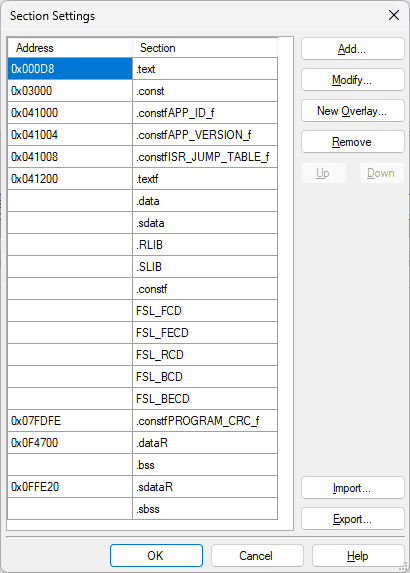
Sections setting: (in
Applicationproject)Address Section 0x041000 .constfAPP_ID_f 0x041004 .constfAPP_VERSIONf 0x041008 .constfISR_JUMP_TABLE_f 0x041200 .textf 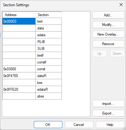
-
The
Bootproject defines the same interrput functions:r_uart0_interrupt_send()andr_uart0_interrupt_receive()as theApplicationproject.When an interrupt is triggered, the interrupt function in the
Bootproject will be executed.However, If I put the redefined interrupt in the
Applicationproject, there will be an error:1(E) E0562142 E0562142:Interrupt table address "0x2c" of ".vect" has multiple definition Blink_P16.mtpjI think that is because I have two same interrupt in the project.
For the example code, I suspected that the
Bootproject and theApplicationproject are compiled separately, and then the two .hex files are flashed separately as well. -
Kaushik said the example code (Dual boot) is different from the situation we are facing.
-
In our project, we do not have access to the
Bootproject (i.e., the Bootloader program). The customer just tell us once an interrupt is triggered, the program will go to some address, where the interrupt function should be stored.For example, when the interrupt
INTTM00(whose Vector Table Address is2C) is triggered, according to the table provided by customer, the program will jump to0x5062. -
So, I think a section containing a function pointer should be put at
0x5062, because I think a “function pointer” will make the program to execute a function. -
The content stored at
0x5062is calling the interrupt function by “de-referencing” the function pointer. -
This section , referring to Manual of CC-RL Page 380.
1 2 3 4 5 6 7 8 9 10 11 12 13 14#include "utility.h" #pragma section INT_TIMER void __far Config_TAU0_0_interrupt(void) { /* Get the address of the relevant jump table entry */ uint32_t addr = *(__far uint32_t *)(ADDR_ISR_TIMER); /* Create a function pointer based on the jump table entry */ void (*app_main_isr_timer)(void) = (void (*)())(addr); /* Call the function */ app_main_isr_timer(); }
- The address of jump table is fixed. So the address of the first cell
(2025-01-22)
-
Use assembly command (Kaushik found this method work after he looked at the asm file in the example project r1-Example)
1 2 3 4 5 6 7 8# jumptable.asm .extern _system_timer_counter ; Declare the external function .section DATA, DATA .org 0x5062 ;interrupt 0x002C -VECTN=2C=5062 BR !!_system_timer_counter ; Store the 16-bit address pointer of the interrupt functionBR(branch) is used for control flow, jumping to far addresses r1-样例.
(2025-01-29)
-
Test LIN transmission interrupt function with Hongsheng’s example code
-
Reasons:
-
I modified the transmission function in Hongsheng’s example code by reading the recepted data explicitly, as the reception buffer doesn’t get data if I copy the source files of LIN functions following his instructions.
I haven’t figured out the problem of integrating the LIN functions. Maybe there is extra operation after copying source files.
-
-
Actions:
- Test the LIN function with BabyLIN
- Check Clock to 40 MHz; Add watchdog (Overflow time: 2^14/fWDT to make 1092, around 1000 ms; Cancel INTWDTI)
- Include the
jumptable.asm, where the generated interrupt functions are called, with the_staticdecorator canclled. - Compile the sample project to a .hex file
- Merge the bootloader and LIN app .hex
-
Results:
-
Go to exception:
ff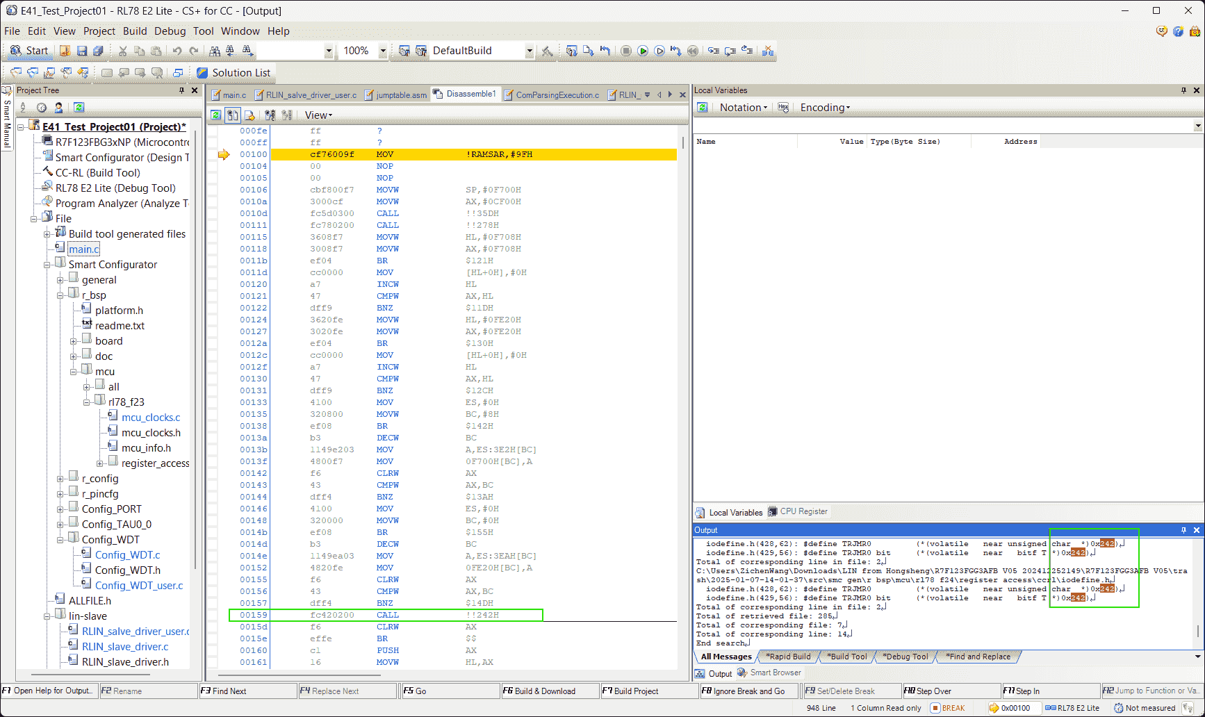
-
I included the
iodefine.hinto the project, but still run intoff. -
The
iodefine.hmay be not necessary, and the other 3 .asm (cstart, hwinit, stkinit, generated by CS+ when creating a new project) either because cstart.asm is already in themcufolder. So, maybe the other 2 are in somewhere else.
-
-
-
(2025-01-30)
-
Replace parts of the customer’s bootloader with the own project bootloader.
-
Reasons:
-
我用 Hongsheng 项目编译生成的 bootloader 部分, 替换了客户 bootloader 中的对应部分,然后 LIN 就能工作了。 (E41_Test_Project01_20250109-Wed\E41_Test_Project01-Wed-Copy_to_Remove_Timer\DefaultBuild)
-
然后我想看到底是哪部分的问题,Hongsheng 项目编译生成的 hex 里面 的 bootloader 部分很简单, 只是 vector table 里面有几个要跳转去的中断函数的地址, 然后在 0x0070 后面有个 Tesla bootloader 没有的 callt table (0x80-0xBF), 然后还有开头的 4 个字节不一样,我就只把这些替换了,LIN 仍然可以工作。
-
-
Actions:
-
0x00C0is the option byte controlling watchdog timer r1-Manual.0x00C6-0x00D5is the Security ID. -
It’s not necessary to modify the customer’s vector table. Only insert the “callt” table and change the program start address to
0x5122, and the end address to0xFFFF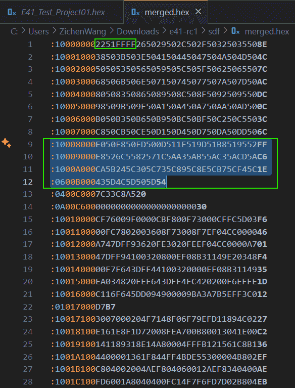
-
The program starts executing from
0x5122.0x50E0is the.text(code) section.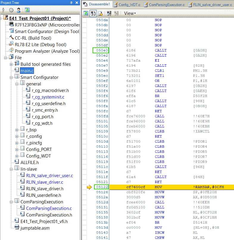
-
-
(2025-01-31)
-
Check the address in the callt table:
-
Reasons:
- What’s the exact difference causing LIN transmission interrupt doesn’t work.
-
Actions:
-
The area 0x80 ~ 0xBF is the addresses of functions.
addr value functions called in app? (ED) 0x0080 0x50E0 _main Y 0x0082 0x50F8 _R_Systeminit N 0x0084 0x50FD _hdwinit N 0x0086 0x510D _bsp_init_system Y 0x0088 0x511F _bsp_init_hardware Y 0x008A 0x519D _R_BSP_GetFclkFreqHz N 0x008C 0x51B8 _start_clock N 0x008E 0x5295 _stop_clock N 0x0090 0x52E8 _set_fclk_clock_source N 0x0092 0x556C _get_fclk_freq_hz N 0x0094 0x5782 _change_clock_setting N 0x0096 0x5A1C _mcu_clock_setup N 0x0098 0x5AA3 _R_Config_PORT_Create N 0x009A 0x5AB5 _R_Config_PORT_UserInit N 0x009C 0x5AC3 _LinSendBreak N 0x009E 0x5ACD _LinSendBreakData N 0x00A0 0x5BCA _RLIN_Slave_Init N 0x00A2 0x5C24 _RLIN_Slave_HeaderReceive N 0x00A4 0x5C30 _RLIN_Slave_Transmit N 0x00A6 0x5C73 _RLIN_Slave_Receive N 0x00A8 0x5C89 _RLIN_Slave_NoResponse N 0x00AA 0x5C8E _Clear_DataBuf N 0x00AC 0x5CB7 _Get_reponse_RxData N 0x00AE 0x5CF4 _ProcessingReceivedData N 0x00B0 0x5D43 _R_Config_WDT_Create N 0x00B2 0x5D4C _R_Config_WDT_Restart N 0x00B4 0x5D50 _R_Config_WDT_UserInit N -
If a function is called, there should be
ED(orEF) + addr- These 2 function
_bsp_init_systemand_bsp_init_hardwarefollowsFC.
- These 2 function
-
-
Results:
- LIN funcstions are declared in the callt table.
-
Analysis:
-
The RLIN module is added by copy & paste source files, instead of generated by smart configurator.
So, maybe those LIN functions are not stored together with other interrupt functions. Thus, the callt table is created to declare them.
-
Renesas support sent a example project for RLIN3. I don’t know if using that can make the LIN functions in normal locations.
However, RLIN3 is also a library, whose code won’t be generated by the Smart Configurator.
-
-
-
Try to don’t use the callt table.
-
Reasons:
- The 4 LIN interrupt functions can be reached by setting the jumptable.asm. Is the callt table used only to make code shorter?
-
Actions:
- Add
__calltkeyword at those functions definition.
- Add
-
Results:
- Adding
__calltwill not change the address of those functions.
- Adding
-
Example UART
References:
-
样例程序–RL78 bootloader via UART for CCRL
- Shared by Chinese Renesas support
Notes:
- Debug can be performed by selecting the
Using Debug ToolasRL78 Simulatorr1-Example.
E2 Lite Debugger
Errors
Prohibited area
Problem:
(2025-01-23)
-
In CS+, when trying to download program to MCU, there is an error:
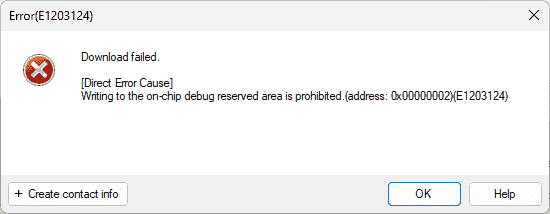
- The E41 project and the LIN project from Hongsheng both encounter this problem:
References:
-
E1203124 error on CS+ when trying to debug RL78 | Renesas Customer Hub
- Searched by
Direct Error Cause] Writing to the on-chip debug reserved area is prohibited.(address: 0x00000002)(E1203124)in DDG
- Searched by
Notes:
(2025-01-24)
-
Set the Linker Options: Devices > Set debug monitor area
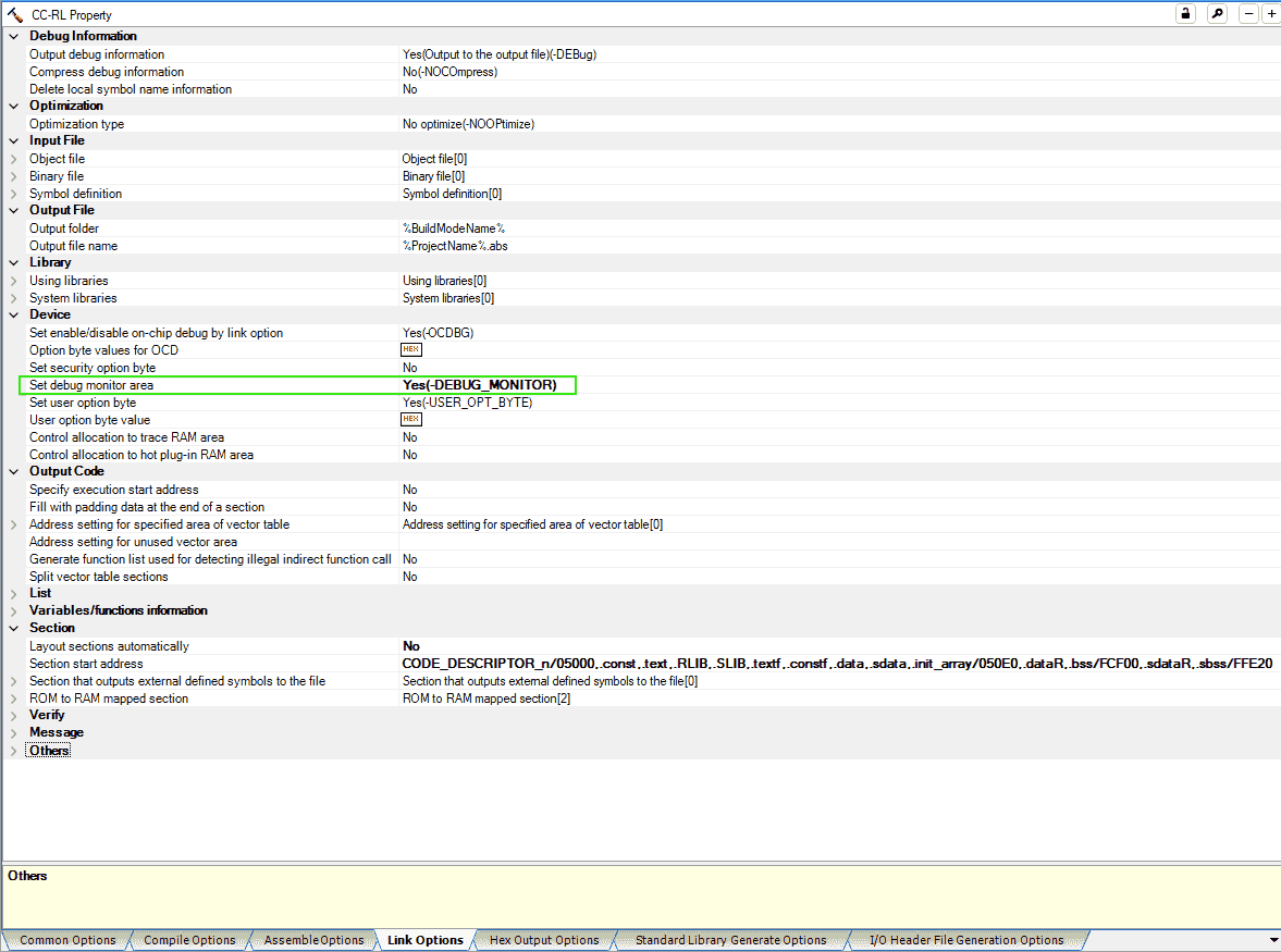
- I found the in-use options are the same as the settings of Hongsheng’s example LIN project. I guess those settings are inheritated from the LIN function. But I don’t know why we can debug his LIN project correctly without modify those settings.
(2025-01-26)
-
The debugger setting is set by Smart Configurator, when generating code.
-
The following prompt occurs when I generate code for a F24 project, after configuring Timer and Port modules.
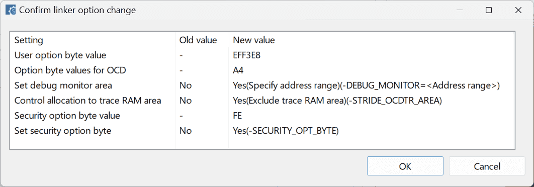
-
Incorrect Secu ID
Problem:
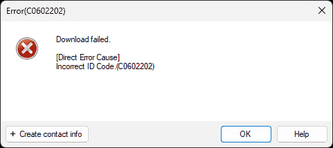
-
After I flash the bootloader provided by customer, I cannot download and debug our project due to an error: “Incorrect ID Code”
References:
-
Error (C0602202) occurs when I debug a RH850-family MCU. (CS+, E2, E1, E20) - Renesas Electronics
- Searched by
renesas Incorrect ID Code.(C0602202)in DDG
- Searched by
- CC-RL Compiler User’s Manual - Renesas Electronics Corporation
-
E1/E20/E2 Emulator, E2 Emulator Lite - Additional Document for User’s Manual - (Notes on Connection of RL78)
- Mentioned in Writing to the on-chip debug reserved area is prohibited? - Forum - RL78 MCU - Renesas Engineering Community
- Searched by
Direct Error Cause] Writing to the on-chip debug reserved area is prohibited.(address: 0x00000002)(E1203124)in DDG
Practices:
(2025-01-24)
-
“This error message is displayed when the security ID (ID code) written in flash memory does not match the security ID specified by the debug tool.” r1-Support
- The security id is written at addresses
0xC4to0xCDr3-Manual, while in the customer’s bootloader, security id is at0xC6to0xD5.
- The security id is written at addresses
(2025-01-26)
-
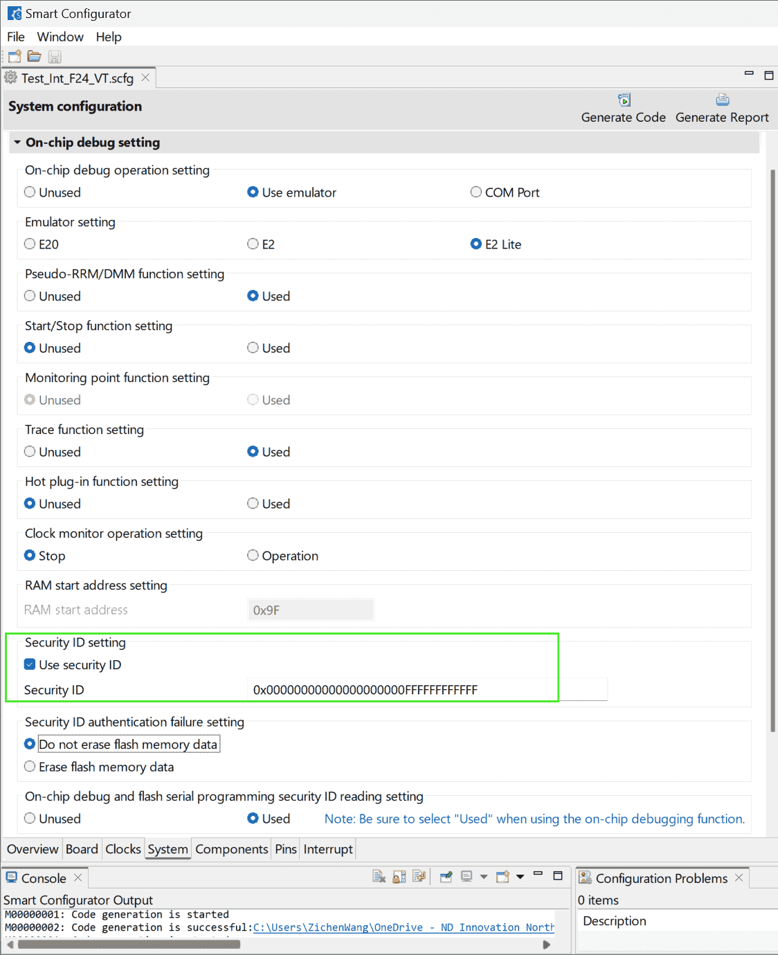
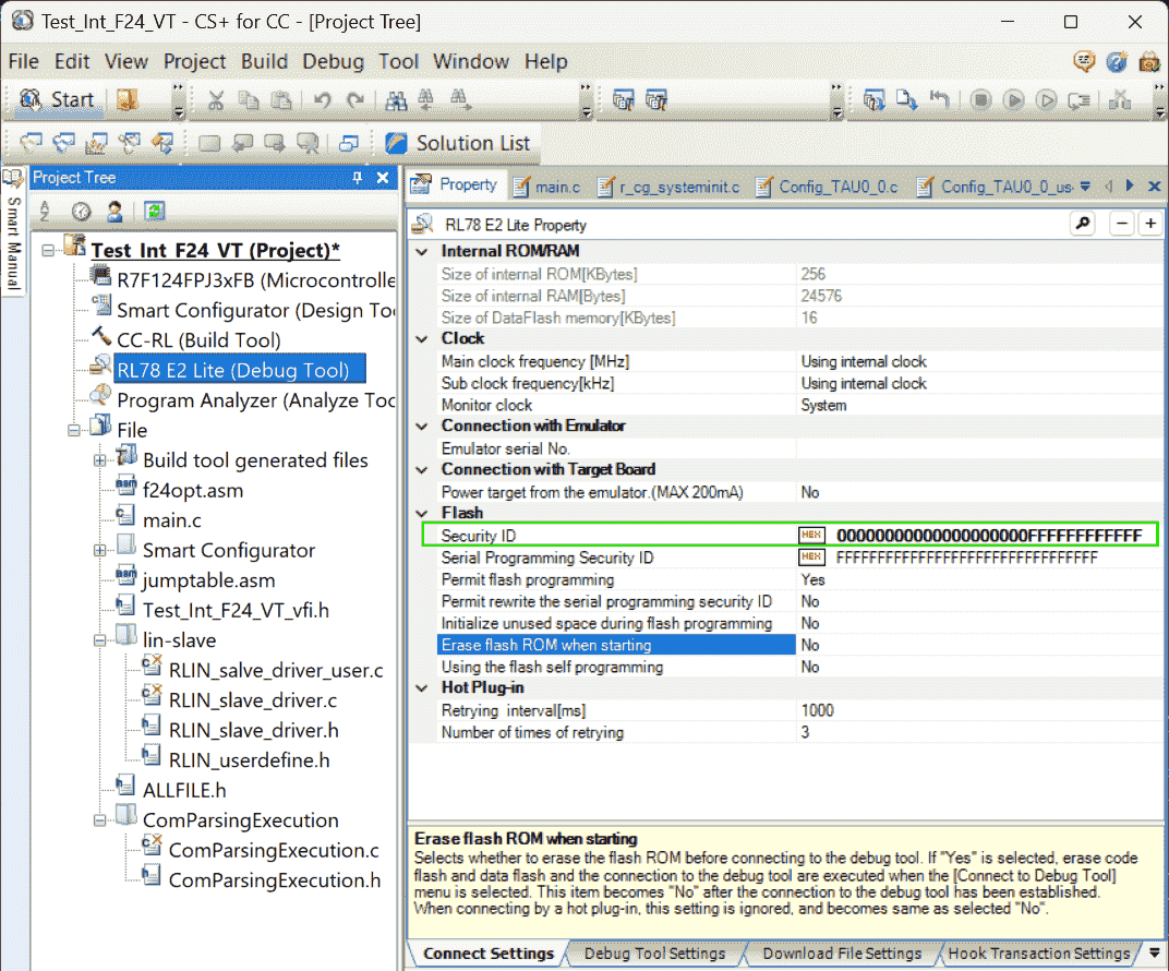
Set up Security ID in Smart Configurator and specify Security ID in the Debug Tool options.
- 16 bytes (32 digits):
0x00000000000000000000FFFFFFFFFFFF(The frist 10 bytes are 0x00, and the rest 6 bytes are set to 0xFF)
-
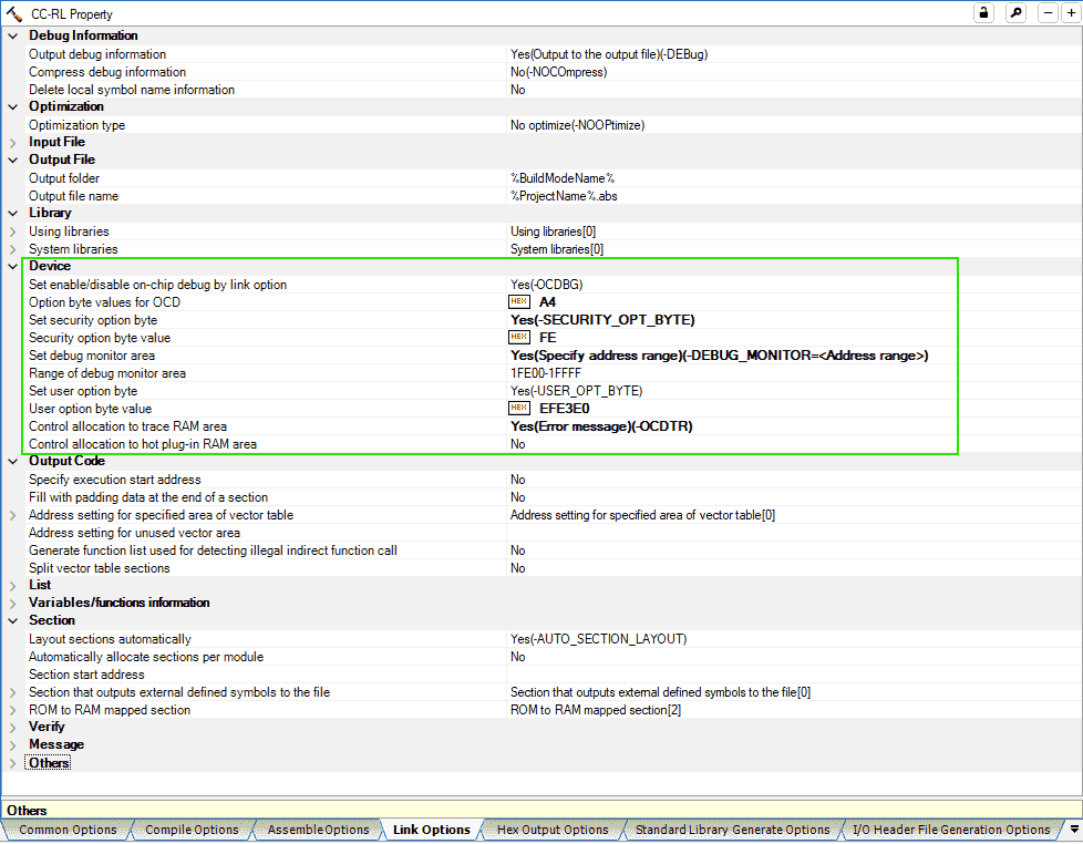
The smcg configure: “Do not erase flash memory data” corresponds to
A5for the “Option byte values for OCD” in the “Link Options” of CS+. -
“Erase flash ROM” can be set to “Yes” to reset the security ID, when downloading failed.
- 16 bytes (32 digits):
-
Rectify the security id in the customer bootloader program.
The security ID in CC-RL of old version V1.09 is of 10 bytes:
1:0A 00C6 0000000000000000000000 30However, we are using a newer version CC-RL V1.15, where the length of security id can be various as long as not exceed the maximum size r2-Manual.
1:10 00C6 00 00000000000000000000FFFFFFFFFFFF 30
Watch Not Real Time
Problems:
- The variables added into the Watch window are not changing in real time.
Notes:
(2025/02/05)
- Use Smart Configurator to re-generate code again. Then, the variables can be updating in real time with pink color.
CLOCK
Problems:
-
Cannot download programs, prompting with an error:
1 2 3 4 5Error(E1200416) Download failed. [Direct Error Cause] No response from the emulation CPU. Please confimm the sighal of the CLOCK or RESET,WAIT and so on.(E1200416)
Notes:
(2025-04-09)
-
The debugger or the MCU is broken.
-
Supports:
-
Sajad took apart the housing of the debugger and check the board, not found visible problem.
-
He was trying to update the firmware of debugger, but he found RFP.
-
Use RFP to flash program as it can provide more information.
(2025-04-15T16:37:19)
- The same error occurs again when MCU is broken while the debug is working.
-
-
Actions:
-
RFP cannot flash either
1Error(E4000004): A framing error occurred while receiving data. (BFW: 0354)
-
-
Results:
- “This debugger is completely gone,” Sajad said after seeing that error.
-
Renesas Flash Programmer
Flash Hex to Micro
Problems:
- Flashing the program into the MCU allows the ECU to start automatically upon power-up, eliminating the need to connect a debugger each time to initiate execution.
Notes:
-
Generate Hex file during building
-
Supports:
- Project Tree -> CC-RL (Build Tool) -> Hex Output Options -> Output File, Hex file format: Intel HEX file
-
-
Flash Hex file
-
Supports:
-
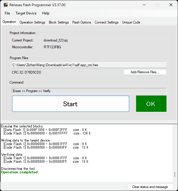
Open Renesas Flash Programmer V3.17.00 -> File -> New Project
-
Project Information: Microcontroller: RL78, Project Name, Project Folder.
Communication: E2 emulator Lite. Microcontroller type will be detected automatically: R7F123FGG
-
Set “Program Files” to the target hex file.
-
Remove all wires connecting with the Debugger to unhold the “Reset” pin. Even the debugger is not power on, the “Reset” still is hold.
-
Connect BabyLIN and send commands.
-
-
Merge Hex
Problem:
-
Downloading two hex files: one is the bootloader, the other is the application program, using software: Renesas Flash Programmer (RFP) doesn’t result in ECU running correctly.
Specifically, the bootloader should handle the INTTM00 interrupt and jump to the ISR in the application program to generate a blinking LED effect. However, by downloading the 2 separate hex files:
LMBR_94xxxxxxx5C_P3_A1_U1_bam_boot_combined.hexandapp_crc.hex, the LED is not blinking. -
Whereas if downloading the application hex file through the provided SDP tool after flashing the bootloader hex using RFP, the ECU shows up correct result: blinking LED.
Notes:
(2025-01-24)
-
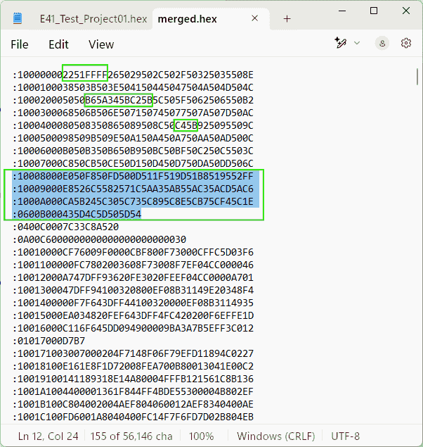
Stitch the bootloader hex file and the application hex file together:
1 2 3 4 5 6 7 8:101ED000AAAAAAAA41268DD4FFFFFFFFFFFFFFFF9A :101EE000FFFFFFFFFFFFFFFFFFFFFFFFFFFFFFFF02 :101EF000FFFFFFFFFFFFFFFFFFFFFFFFFFFFFFFFF2 :101F0000FFFFFFFFFFFFFFFFFFFFFFFFFFFFFFFFE1 :081F1000FFFFFFFFFFFFFFFFD1 :105000004F0003010100000055AA55AA55AA55AA50 :10501000FFFF000005000000F3500000DC800000EE :105020000000000000000000000000000000000080-
Kaushik copied all content in the bootloader hex file:
LMBR_94xxxxxxx5C_P3_A1_U1_bam_boot_combined.hexand pasted it on the top of
app_crc.hex, after deleted the last line of the bootloader:1 2 3 4 5 6 7 8# The original LMBR_94xxxxxxx5C_P3_A1_U1_bam_boot_combined.hex ..... :101ED000AAAAAAAA41268DD4FFFFFFFFFFFFFFFF9A :101EE000FFFFFFFFFFFFFFFFFFFFFFFFFFFFFFFF02 :101EF000FFFFFFFFFFFFFFFFFFFFFFFFFFFFFFFFF2 :101F0000FFFFFFFFFFFFFFFFFFFFFFFFFFFFFFFFE1 :081F1000FFFFFFFFFFFFFFFFD1 :00000001FF -
只需要把客户提供的 bootloader 的 hex file 和 我生成的 app code 复制粘贴到一起, 就是一份完整的 hex file,不需要使用客户提供的专用的 SDP 工具。Kaushik 把 bootloader 的 最后一行删了
-
bootloader hex 和 app hex 不能是分开的两个单独的文件通过 Renesas Flash Programmer 下载, 而应该先合并(删除bootloader 的最后一行)成一个 hex,再下载
-
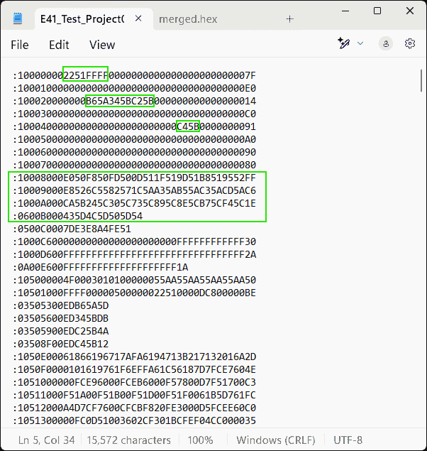
合并之前,需要对 Application project 编译生成
Blink_P16_VT.hex做处理, 首先需要把开头的 vector table.vect删了, 然后补全 hex file 中的 gap,用 0 填充, 最后计算 crc,并且放到指定地址,从而得到app_crc.hex。1 2 3 4 5# app_crc.hex :105000004F0003010100000055AA55AA55AA55AA50 :10501000FFFF000005000000F3500000DC800000EE :105020000000000000000000000000000000000080 .....
-
Web Simulator
References:
-
RL78 Web Simulator
- Found in Software and Tools
- which is the parent dir of Smart Configurator Videos for RL78 Family
Notes:
(2024-11-08)
- Web simulator was released on Nov 05.
On Ubuntu
(2025-05-23T18:05)
-
E2 studio on Ubuntu 24.04
-
References:
-
Renesas VS Code Extension
-
Problems:
- Use VSCode IDE to build and debug a Renesas project
-
Supports:
- Renesas VSC extension can monitor Local, Registers, Watch, and Call stack r1-Present
::: aside
:::References
{{{ 1. [Visual Studio Code: How to Create, Build, and Debug Smart Configurator Project for RL78 - RenesasPresents](https://youtu.be/Y_nR5R029Q4)
Searched by `renesas rl78 f23 I2C IICA configuration` at [DDG Videos](https://duckduckgo.com/?origin=funnel_home_bing&t=h_&q=renesas+rl78+f23+I2C+IICA+configuration&ia=videos&iax=videos&iai=https%3A%2F%2Fwww.youtube.com%2Fwatch%3Fv%3DY_nR5R029Q4) 2. [8. Quick Start for Renesas RA — Renesas VS Code Extensions 1.0.0 ...](https://www2.renesas.eu/_custom/software/ree_eclipse/vscode/docs/quick-start-ra.html)
Searched by `renesas smart configurator for ubuntu` at [DDG](https://duckduckgo.com/?q=renesas+smart+configurator+for+ubuntu&ia=web) }}}