Table of contents
(2024/11/16)
- Feature image is from: iDoka/awesome-linbus
- Included by lin · GitHub Topics · GitHub
- Searched by LIN Protocol — One Wire Protocol for Automotive Applications - Electronics Lab in Google image
- Init search by
lin protocolin DDG
① Overview
References:
-
LIN Bus Explained - A Simple Intro (2023) - CSS Electronics
- Chinese LIN总线简介 - bilibili - 广州虹科电子
- Found by searching
lin总线in biliibli.
- LIN protocol 2.2A- Specification Package - lin-cia.org
Notes:
-
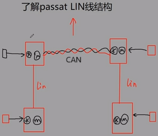
Single signal wire: Master sends request to the bus, and slaves send response to the bus.
- Example of the Left-hand side Front door module controls the rest 3 windows r1-bili:
-
Only one task exclusively occupies the bus at a time.
-
A suppliment bus of CAN
-
Control window, wiper, door
-
One master task and 16 slave tasks (including master node)
-
Master task means publishing header, which can only be done by the master node.
-
Slave task means sending data. Slave node can only publish data, but they can’t publish header.
-
-
Low-cost, low-speed with potential delay, requiring response space
② Frame Structure
References:
- 4.25 LIN线控制的车窗玻璃如何下降 - bilibili - 虹科Pico汽车示波器 Followed by v2
- 【汽车总线技术】LIN总线技术基础讲解合集 - bilibili - 广州虹科电子 - 33:50
-
LIN Protocol Specification Revision 2.2A (Dec 31, 2010)
- Pages: p.30
Notes:
(2024-10-07)
-
A complete packet can be divided into 5 parts:
-
Break field (A long period of dominant value, at least 13 dominant bits) for letting slaves be aware of there is a frame on the bus.
- One break field followed by 4 to 11 byte fields r3-Docs-p.29, including: Sync, PID, 1-8 Data, checksum
-
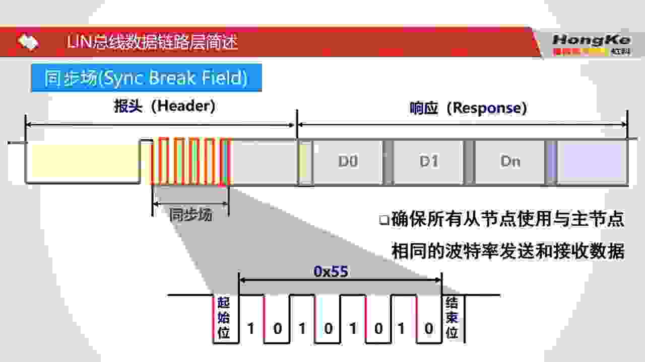
Sync: 1 byte
0x55(0101_0101). Note that the waveform on bus is reversed: 1010,1010 r2-Bili- Slaves’ clock are syncronized based the falling edges. That’s why the 1010,1010 is used.
-
Protected ID
-
Data field
-
Checksum
-
-
Packet diagram:
packet-beta title A LIN Frame carried 2 bytes of data 0-12: "Break Field" 13: "Break delimiter" 14: "Start bit (0)" 15-22: "Sync (0x55)" 23: "Stop bit (1)" 24: "Start bit" 25-32: "PID (8 bit)" 33: "Stop bit" 34: "start bit" 35-42: "1 data (8 bit)" 43: "Stop bit" 44: "Start bit" 45-52: "1 byte data" 53: "Stop bit" 54: "Start bit" 55-62: "Checksum" 63: "Stop bit"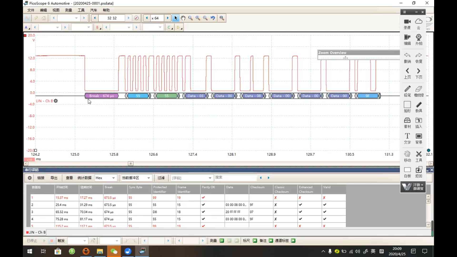
-
Terminologies:
-
Every byte field is enclosed by a Start bit 0 ahead and a Stop bit 1 at the end. r3-Docs-p.29.
-
Byte fields refer to 4 types of field: Sync field, Protected id field, each Data field. Whereas the Break field is at least 14 bits, which is the only field that doesn’t comply the structure of a byte field. r3-Docs-p.30.
-
Frame length should be calculated as a sum of two portaions: Header + Response, as the response can be published by a slave r3-Docs-p.32.
- The time of sending a frame counts not only sending bits, but also the “Response space” and “Inter-byte spaces”.
- There is an “inter-byte space” betwen every 2 “Byte file”. The gap betwen Break field and the Sync field is not an “inter-byte field”, because the Break field is not a “Byte field”.
-
-
0 is dominant value, while 1 is recessive value.
-
If the data field is empty, this packet is called a Hearbeat packet, used to inform salaves that the master is online and keep the salves aweak.
-
Distinguish master and slave from the waveform: the master is of lower voltage, while the slave’s lower bound is higher.
- The bottom edge of the packet published by the master node is flat. While the packet carrying slave’s data has a lader.
-
A complete dialog (cycle) between master and a slave consists of 4 packets:
-
Sequence diagram for a conversation:
sequenceDiagram Master->>Slave: Heartbeat packet Note over Master,Slave: Wait Master->>Slave: Instruction packet Note over Master,Slave: Wait Master-->>Slave: Request packet header Slave-->>Master: Response Note over Master,Slave: Wait Master-)Slave: Following Instruction
-
Protected ID
References:
- LIN通讯_报文帧结构的PID及数据段 - HappytoShare Followed by v1
Notes:
-
A 1-byte (8 bits) protected identifier field includes: 2 bits for parity and 6 bits for frame identifier
-
Frame ID ranges from 0 to 63, corresponding to hex code: 0x00 ~ 0x3F, where the 2 frames: 0x3C (60) and 0x3B (61) are used to carry diagnostic and configuration data. And 0x3E and 0x3D are reserved for future protocol enhancement.
- 6 frame types:
FrameID 0-59 60 Type Unconditional
- 6 frame types:
-
Each frame id corresponds to a unique Protected ID, so a lookup table can be used in programs. LIN总线代码详解-1 - 20:52
-
-
2 Parity calculation based on Exclusive OR ⊕ and NOT ¬:
-
P0 = ID0 ⊕ ID1 ⊕ ID2 ⊕ ID4
-
P1 = ¬ (ID1 ⊕ ID3 ⊕ ID4 ⊕ ID5)
-
-
The frame identifier ranges 0 ~ 63, resulting 64 types of frames.
-
Transmission starts from ID0 upwards to P1
-
Examples:
-
Given a frame identifier: 38 (10_0110)
P0 = 0 ⊕ 1 ⊕ 1 ⊕ 0 = 0
P1 = ¬ (1 ⊕ 0 ⊕ 0 ⊕ 1) = 1
Protected Id = 1010,0110
The wave on bus:
-
Data Field
-
A frame can carry 0 ~ 8 bytes of data. Each data is a byte field.
A byte field is 10-bit length (SCI format):
-
Bit transmission starts from d0 and ends at d7
For example, a data is
0101,1110The wave on bus is:
Checksum
(2024-10-09)
-
Two types of checksums:
-
Classic checksum is a sum of all Data bytes without including the protected id field;
-
Enhanced checksum sums up all Data bytes including the protected id.
-
-
The frames in LIN version 1.x use Classic checksum. Whereas the frames LIN version 2.x use Enhanced checksum.
Note the diagnostic frames (0x3C & 0x3D) always use the classic checksum because their IDs are fixed. HKACO - 41:00
-
Checksum calculation when assembling the frame before transmission:
-
Sum up all Data fields
- Since the checksum is only of 1 byte (8 bits), once an intermediate sum got larger than 255 (more than 1 byte), a 255 (0xFF) needs to be subtracted.
-
Flip all bits of the sum.
-
-
Validate the checksum once the receiver received the frame.
- Sum up all Data, but not followed by flipping all bits;
- Add the Data sum to the frame checksum, expecting their sum is 0xFF.
-
Example:
Given a frame to be published on the bus:
- Break field: 13 bits of 0 and 1 bit of 1;
- Sync field (8 bits): 0101,0101 (0x55);
- Protected id (8 bits): 1010,0110 (0xA6), if the frame id is 38;
- Data (length varies from 8 to 64 bits), e.g., 1001,0011 (0x93, Decimal: 147)
Then, the checksum to be appended is:
-
Sum all Data: 1001,0011 (smaller than 0xFF, which is not needed to be subtracted)
-
Flip all bits
-
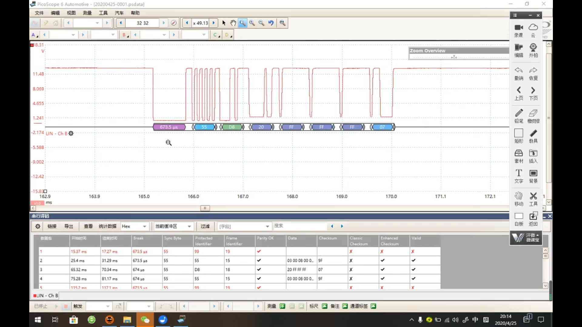
Example 1: Two Unconditional frames with LIN 2.2A HappytoShare - 07:47
FrameID PID Data1 Data2 Data3 Data4 Data5 Data6 Data7 Data8 V2 DL 0x30 0xF0 0x00 0xFF 0x0F 2 0x31 0xB1 0x00 0x00 0x59 0x53 0x7f 0x14 0x00 0xff 0x0E 8 -
Extended checksum:
+data2 +PID Inverted Add 00 00 F0 + FF + F0 —– —— —— Sum FF F0 0F Sub 00 Frame ID: 0x31
+data2 +data3 +data4 +data5 +data6 +data7 +PID Inverted Add 00 00 59 AC 2C 40 40 F1 + 00 + 59 + 53 + 7f + 14 + ff + B1 —— —— - - - - - - Sum 00 59 AC 12B 40 - F1 Sub 2C 40 0E -
Subtracting 0xFF (256) can be figuratively performed by: removing the highest 1 (meaning 256) and add 1. HKACO - 42:20
-
Flip 0xF1 (1111,0001) -> 0000,1110 (E)
-
-
Waveform
Problem:
- Use the logic analyzer: “Saleae Pro 8” to prob a LIN header transmitted by the Master RL78/F24
References:
-
逻辑分析仪 Saleae Logic 16使用 - 程序员老吴的文章 - 知乎
- Searched by
逻辑分析仪 用法in DDG
- Searched by
-
logic-lin-data/README.md at master · ma-lwa-re/logic-lin-data - GitHub
- Searched by
Saleae for LIN protocolin DDG
- Searched by
Notes:
(2024-12-16)
-
Prob a LIN frame using Saleae logic analyzer r1-知乎
- Actions:
-
Extension for parsing LIN frame r2-GitHub
-
Oscilloscope
-
References:
-
Actions:
- Send LIN frame
-
Results:
(2025-07-16T17:06)
-
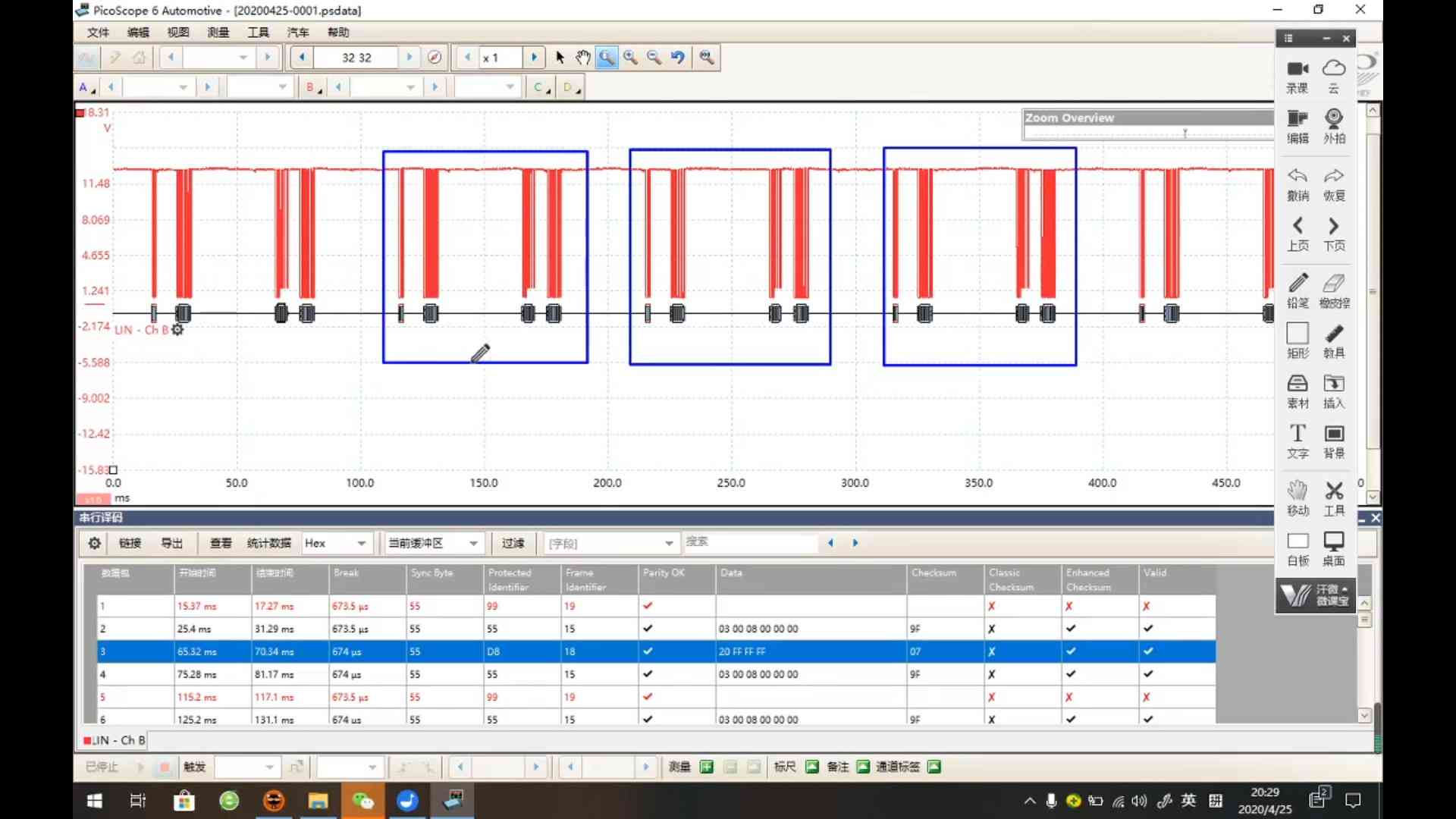
A 0x29 frame and a 0x47 frame without response.
- 1 bit duration is around 50~60 us
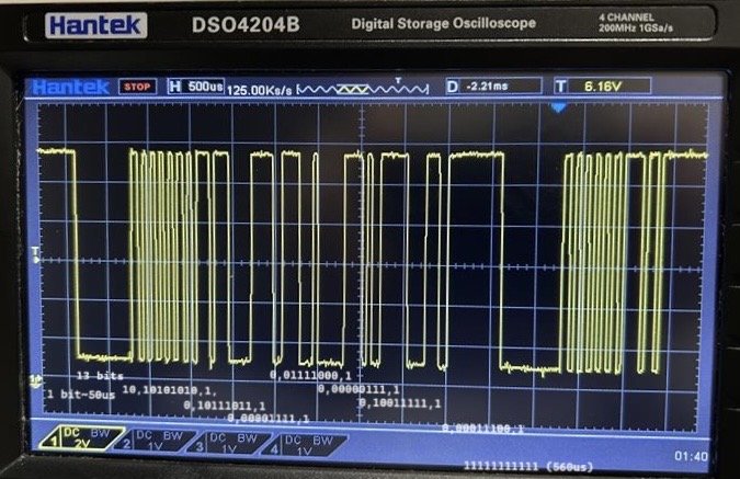
1
2
3
4
5
6
7
8
0 1 1 0 1 0 1 0 1 0 1 0 1 0 1 0 1 1 1 0 1 1 1 0 0 0 0 0 1 1 1 1 1 0 0 1 1 1 1 0 0 0 1 0 | | | | | | | | | S S S S S S S S S t t t t t t t t t o a o a o a o a o p r p r p r p r p t t t t Sync PID=0xDD Data 0 = F0 Data 1 = 1E-
PID = 0xDD, corresponding to the frame ID 29 r1-LUT
-
The PID field in the second frame is
0b01101111(i.e., reversed0b1111,0110),0x6F, corresponding to frame ID 47
(2025-07-17T09:37)
-
A
0x50frame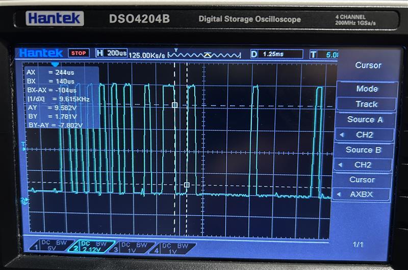
Note:
- The waveform displayed on the osilloscope is reversed from the signal.
- There might be some recessive bits (
1) after the end bit of the last byte field. And the following first0is the start of the next byte field.
1
2
3
4
5
6
7
8
0 0 1 1 0 1 0 1 0 1 0 1 0 1 0 0 1 0 0 1 1 0 0 1 0 0 0 0 0 0 0 0 0 1 0 0 0 0 0 0 0 0 0 1 | | | | | | | | | s s e s s s s s s t t n t t t t t t o a d a o a o a o p r r p r p r p t t t t Sync = 0x55 PID=0x32 Data 0 = 0 Data 1 = 0- Sync field: 0101,0101 (0x55)
- PID: 0011,0010
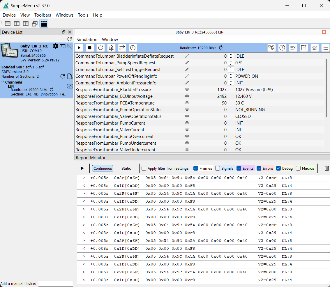
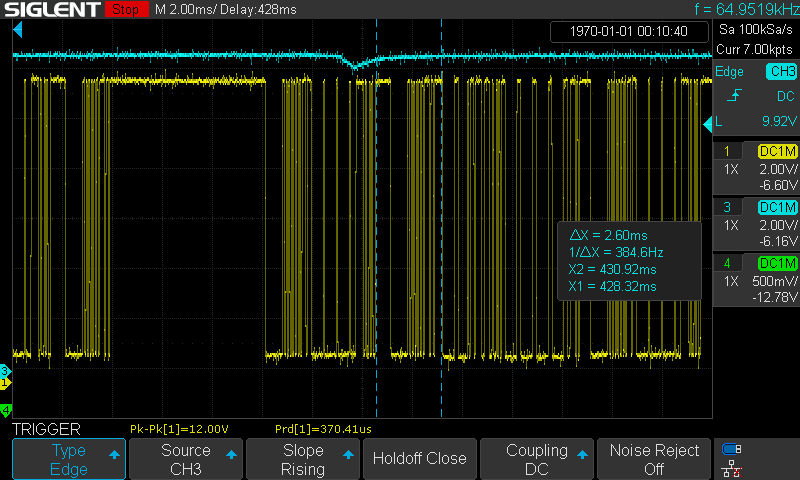
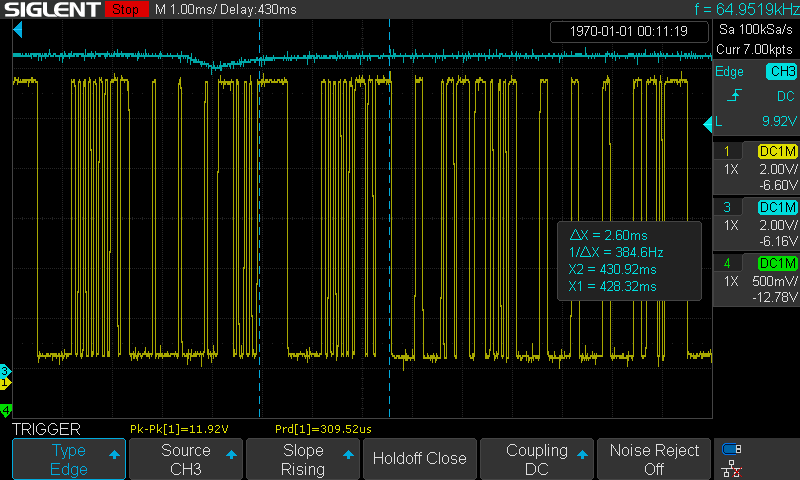
(2025-08-19T10:30)
-
Master header + Master data followed by Master header + Slave data
-
LIN messages:
-
The time interval between the end of a command frame and the start of a response frame

-
Time interval between the start of a command frame to the start of response data

-
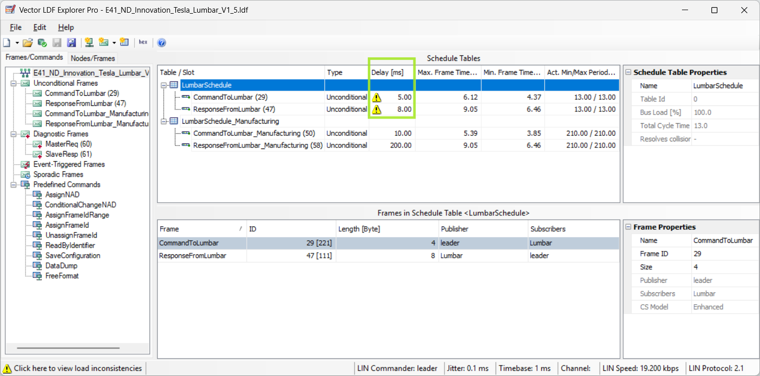
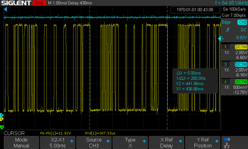
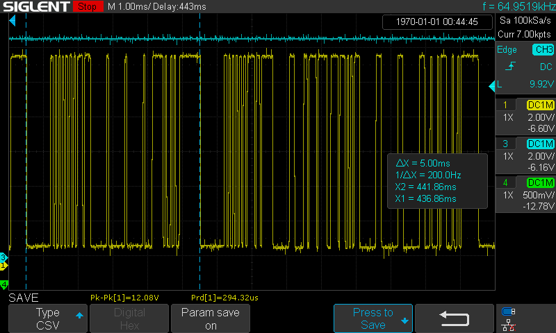
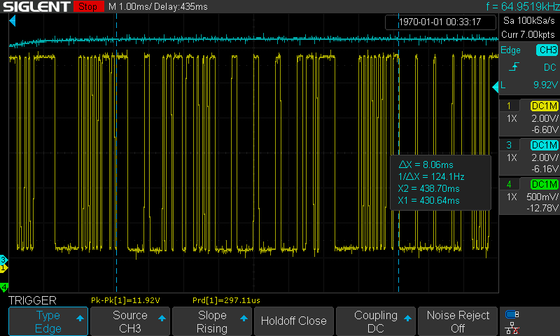
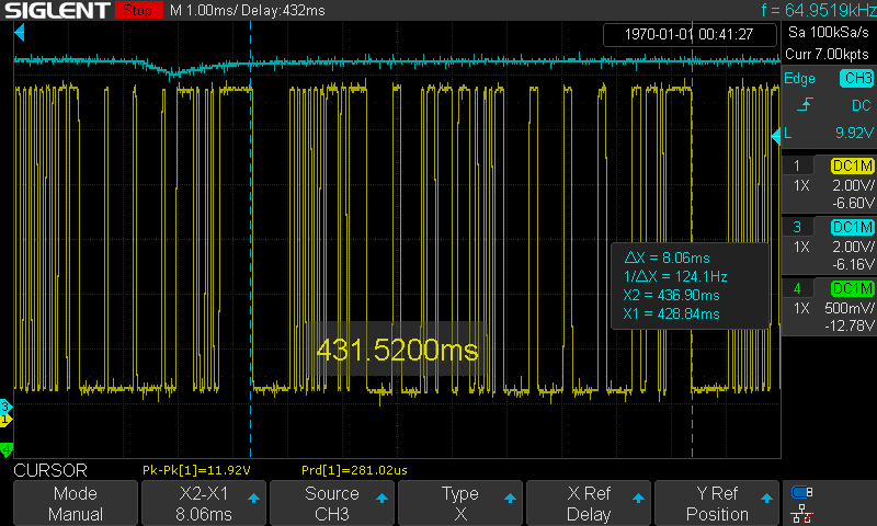
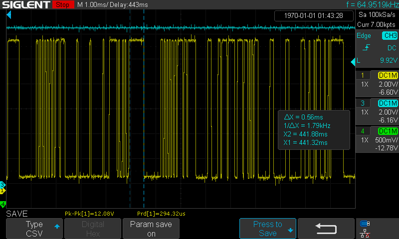
A Master frame occupies the bus for 5ms, A Request frame take up the bus for 8ms:
-
Time length of a Master frame
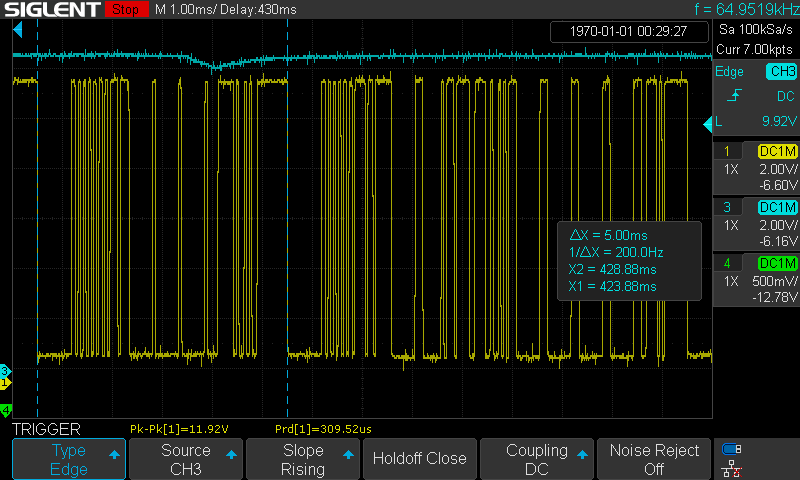
-
Time length of a Response frame
-
Time from the end of the command frame to the start of the response frame

-
Time after the master releases the bus
-
Time length of 13 bits

-
Time length of 8 bits: 1010_1010

-
-
-
③ Frame Transfer
(2024-10-09)
Sequence:
-
Request frame (header + data) published by the master node.
-
Wait some time for slaves recognizing and processing
-
Master node publish a header asking information
-
One of the 15 slave nodes publishs its data on the bus.
Sleep and Wakeup
④ Diagnostic
References:
- 【汽车总线技术】LIN总线技术基础讲解合集 02 汽车LIN总线诊断及节点配置规范 - 广州虹科电子
- 【汽车总线技术】LIN总线技术基础讲解合集 04 LIN自动化测试软件高级功能使用 - 广州虹科电子
- LIN Diagnostic Spec - Revision 2.2A - December 31, 2010; Page 73
- LIN Diagnostic Spec - Revision 2.2A - December 31, 2010; Page 85
Frame Structure
Overall:
-
Both MasterReq and SlaveResp can be a single frame
SFor multiple frames (first frameFF+ consecutive frameCF)1 2 3 4 5 6 7.-- SF .-- MasterReq-+ Diagnostic | '-- FF + CF frame -+ | .-- SF '-- SlaveResp-+ '-- FF + CF
Single Frame
(2025-02-24)
Notes:
-
Data field contains 8 bytes P02-11:52:
- The first 2 data bytes are occupied by NAD (Node address) and PCI (protocol control information), so one frame can only carry 6 bytes data (48 bits) at most.
-
A MasterReq is a single frame:
- Byte0 is
SID(service ID)
- Byte0 is
-
A SlaveResp is a single frame:
-
NAD: Node Address
NAD Description 0 Sleep Command 1 - 125 (0x01 - 0x7D) Physical address of slave node 126 (0x7E) Function Address, 只在诊断报文中使用,不允许用在节点配置中 127 (0x7F) Broadcast address 128-255 (0x80-0xFF) Customized -
PCI indicates the type of 3 kinds of PDU:
SF(single frame), FF (first frame), and CF (consecutive frame) r1-虹科type b7, b6, b5, b4 b3, b2, b1, b0 SF 0 0 0 0 有效数据字节数 FF 0 0 0 1 有效数据字节数的高 4 位, 会与后面的 LEN组成一个 12 位的data: max:FFFCF 0 0 1 0 包编号 -
If the data is less than 8 bytes, a
SFis enough. Otherwise, there will beFFandCF -
第一个 CF 的包编号是
0x1 -
Examples:
0x06= SF + 6 Bytes,0x10= FF + less than 255 (FF) Bytes,0x21= CF + pdu index is 1.
-
-
SID (Service Identifier) P2-25:52
-
Used in MasterReq
-
Two kinds of services: Diagnostic and Node configuration
|Values | Services |
-
First, Consecu Frame
-
A MasterReq is a First Frame + multiple Consecutive frame:
-
LENis an additional segment added in the single frame, while reducing one data byte field. -
Similarly, the First Frame for a SlaveResp is included
LENbased on the single frame of a SlaveResp
-
-
The consecutive frame
CFstructure in the MasterReq and SlaveResp is the same: containing 6 data byte fieldpacket-beta title CF (Data Field) 0-7: "NAD" 8-15: "PCI" 16-23: "D1" 24-31: "D2" 32-39: "D3" 40-47: "D4" 48-55: "D5" 56-63: "D6" -
Example log in SimpleConf console:
FrameID Data 0x3C 0x7f, 0x10, 0x19, 0xaa, 0x01, 0x02, 0x03, 0x04 0x3C 0x7f, 0x21, 0x05, 0x06, 0x07, 0x08, 0x09, 0x10 0x3C 0x7f, 0x22, 0x11, 0x12, 0x13, 0x14, 0x15, 0x16 0x3C 0x7f, 0x23, 0x17, 0x18, 0x19, 0x20, 0x21, 0x22 0x3C 0x7f, 0x24, 0x23, 0x24, 0xff, 0xff, 0xff, 0xff 0x7f: NAD = Broadcast address, informing all nodes0x10: PCI = First frame, no more than0xFFbytes data0x19: LEN, Length (Number of byte of data) = 25 bytes0xaa: SID, Service ID0x01-0x04: Data = 4 byte in the First Frame0x21: PCI =CF, PDU index is0x1- 25 bytes data is from
0xaato0x24
Node Configuration Services
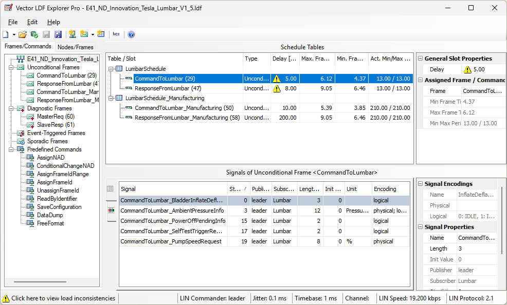
(2025-02-24)
-
Objective: Modify the
NADor Protected ID using the 0x3C frame with Service IDs ranging from0xB0~0xB7r1-02- Each service corresponds to a master request, and is transmitted as a single frame
SFr3-Docs
- Each service corresponds to a master request, and is transmitted as a single frame
Example 22 Service
Notes:
(2025/02/24)
- SID = 22 r1-02-1:10:19
UDS Services
Notes:
Send Diagnostic Frames
(2025-02-14)
Notes:
-
“RAW” vs “DTL” r1-02
- RAW: Type 8 bytes for each frame manually.
- DTL: Enter the total number of data bytes, followed by inputing the data values only, without repeatedly typing the NAD and PCI, as they are identical for a diagnostic frame. The entire data will be split into a First Frame and multiple Consecutive Frames.
-
Protocol > Execute service r2-虹科
⑤ Physical Layer
Clock Freq
(2024-10-10)
-
Bit Timing
-
T0 is the first falling edge, and T1 is the last falling edge in the sync field.
-
Therefore, the length of a bit is:
$\frac{(T1-T0)}{8}$
- If the buad rate is 19,200, the bit timing is 52 us
-
Lin Driver Receiver
Linworks
(2024-10-11)
- 搭配硬件:上位机 (Babylin)
STM32-LIN
(2024-10-08)
References:
- LIN总线代码详解-1 - bilibili - bili_17503743935 Followed by v1)
RL78/F23
References:
-
RL78/F23, F24 Setup Procedure for LIN Communication in Slave Mode (Guidance)
- Searched by
No option for R7F123xxx in renesas lin configuratorin Google
- Searched by
- RL78/F23, F24 Setup Procedure for LIN Communication in Master Mode (Guidance)
-
How to Create a LIN Project with Smart Configurator on e² studio - YouTube - RenesasPresents
- Shared by Kaushik
-
RL78/F2x RLIN3 Module- Software Integration System
- Generated by Smart Configurator
Notes:
(2024-11-13)
-
The Master-mode settings of a RL78 in the r2-Docs p.3 is consistent with the video: r3-YouTube
- fCLK = 40M MHz, Use Pin13 & Pin14
Example: R78/F12 UART
References:
-
RL78G13 Utilising the Serial Array Unit (SAU) in LIN Communications Sample Code - R01AN0912EG0100 (Nov 23, 2011)
- Searched by
Renesas LIN function example codein DDG - Also can be searched by the document number in Search | Renesas
- Searched by
-
RL78/F12 LIN Slave Mode (UARTF) - Renesas - R01AN1839ED0100 (Sep 25, 2013)
- Searched by s1
- Also can be searched by
LIN communication slave modein Search | Renesas - Pages: p.3 p.4
-
Search | Renesas
- Answered by Where to find sample code for RL78/G14 UART - Forum - RL78 MCU - Renesas Engineering Community
- Searched by
Code Utilising the Serial Array Unit (SAU) in LIN Communications site:renesas.comin DDG
- Universal asynchronous receiver-transmitter - Wikipedia
- LIN Protocol Specification - Revision 2.2A (December 31, 2010)
Notes:
(2024-11-19)
-
Tutorial for a CubeSuite+ project (
LIN.mtpj) demonstrates the usage of a SAU module implementing LIN communication r1-SAU. -
Sample code of the UARTF module on an RL78/F12 (Slave mode) communicating with an RL78/F14 (Master) through the LIN Driver r2-RL78/F12.
(2024-11-20)
-
UART is different from LIN r2-p.3 in terms of aspects for a protocol r4-Wiki:
Features UART LIN #wires 2 (Tx-Rx) 1 (Mst-Slv) Direction Full-duplex Half-duplex Syncronize Baud rate Baud rate Signals TTL Distance 40 m Dominant -
They both have No Clock wires, so the waveform-parsing syncronization is achieved by the baud rate between the two parties of the communication.
-
As LIN is used for the situation that one master controlling multiple slaves, so it only has a single wire.
-
Since there is only one single wire shared by the many “users”,
-
Only the master can send frame Headers. When the master is about to publish a frame header, it pull down the bus for 13 dominant bits followed by at leat 1 recessive bit as a break delimiter.
-
The header issued by the master includes two fields: a Sync field and a PID. r5-Lin-p29
-
The baud rate is inicated by the “Sync break field” (
0x55) to enable the target slave to match up its baud rate. -
The PID field is used for generating interruptions, which can be generated after a slave received the PID completely (as PID only can be sent by the Master) r-F12-p4.
-
-
The slave response is of 9 bytes at most:
The reponse consists of two portions:
- 8 bytes data at the most
- 1 byte of Checksum
-
-
Sample Code:
(2024-11-19)
-
init function
-
Reasons:
-
Analogous to Arduino’s
Serial.begin(19200). -
No user operations are required. The code on the slave will keep running: waiting for the header from the Master.
-
The LIN transceiver must be use with a UART?
-
The UART of an MCU need to be initialized: Clock, baud rate, enable interrupts, header format.
-
-
Call APIs
References:
- RLIN3 Module Software Integration System
-
【AutoSAR】只讲干货!一文看懂LIN通信_lin通讯-CSDN博客
- Searched by
l_sys_initin baidu - Select the word:
l_sys_initin the r1-Manual P.100 > 豆包桌面版: “AI搜索”
- Searched by
-
LIN Middleware - GitHub Pages - Infineon.github.io
- Searched by
#define ld_send_message(ch, length, NAD, data) ApMLinDiag_vogSendMessage_DMY(ch, length, NAD, data)in DDG
- Searched by
-
LIN 入门 - Renesas Electronics (Oct 25, 2010)
- Searched by
l_sys_init() LIN 通信代码in Google
- Searched by
Notes:
(2024-12-04)
- The functions of the library rlin3 are not many r4-Manual Ch8.
(2024-12-26)
-
A scheduler is necessary to master r1-SIS.
- A scheduler can be implemented with a timer
(2024-12-27)
-
Add the the lin conf (
/src/r_rlin3_lib/r_lin_drv/Channel0/conf) into compiler. Otherwise, the following code will run into an error:Undefined external symbol "_l_sys_init"-
Actions:
-
The following code can be built without errors:
1 2 3 4 5 6 7 8 9 10 11 12 13 14 15 16 17 18 19#include "r_smc_entry.h" #include "conflin_0.h" int main (void); int main(void) { EI(); // Initialize the LIN core if (l_sys_init()) { // Initialization successful } else { // Initialization failed } // Your application code here return 0; }
-
-
-
Execute processes based on the returned initialization result
-
Reasons
-
l_sys_init()is an alias for theApMLin_u1gInitSys()(hintted by VSCode copilot).- Prompt: “@workspace How to use this function: l_sys_init()?”
-
-
-
Call the LIN2.1 API in an individual source file for a channel.
-
Reasons:
-
The r1-Manual P.33 mentioned the source code for each channel should be separated.
-
-
Actions:
-
Creat a hardware layer source file
 1
 2
 3
 4
 5
 6
 7
 8
 9
10
11
12
13
14
15
16
// hw/lin_channel_0.c #include "conflin_0.h" u1 init_lin_ch0(void) { if (l_sys_init()) { // return L_FAIL; } else { return L_SUCCESS; } }
-
-
-
The difference between
l_bytes_wrandld_send_message()-
Reasons:
-
The r1-Manual doesn’t contain explanation about
ld_send_message() -
conflin_0.h:1 2 3#define ld_send_message(ch, length, NAD, data) ApMLinDiag_vogSendMessage_DMY(ch, length, NAD, data) #define l_bytes_wr ApLin_vogWriteBytesSig
-
-
Actions:
l_bytes_wris used to write a byte to a signal, contributes to a frame r4-入门 P.51.ld_send_messageis used to send a diagnostic frame r3-infineon
-
Analysis:
- I guess the frames are sent automatically according to the schedule:
l_sch_tick().
- I guess the frames are sent automatically according to the schedule:
-
(2024-12-29)
-
A schedule is created and the variable is generated by LIN Configurator, defined in
conflin_0.h-
Reasons:
-
Call
l_sch_set(LIN_CHANNEL0, SCH0, 0U);after initializing LIN r1-Manual p40. -
The LIN transceiver needs +12V battery
-
-