Table of contents
Feature image from Arduino - LED - Blink | Arduino Tutorial - Arduino Getting Started
(Searched by arduino blink led experiment in DDG
)
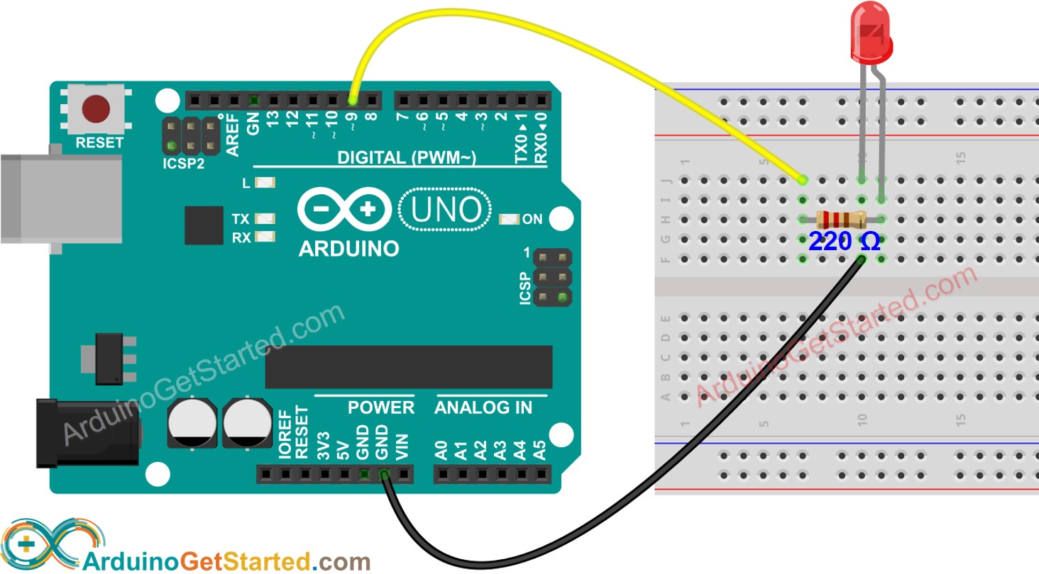
Burn LED
(2024-10-28)
-
I broke an LED because I connected the LED directly with 3.3 V without using a current-limiting resistor.
- A typical current through an LED is
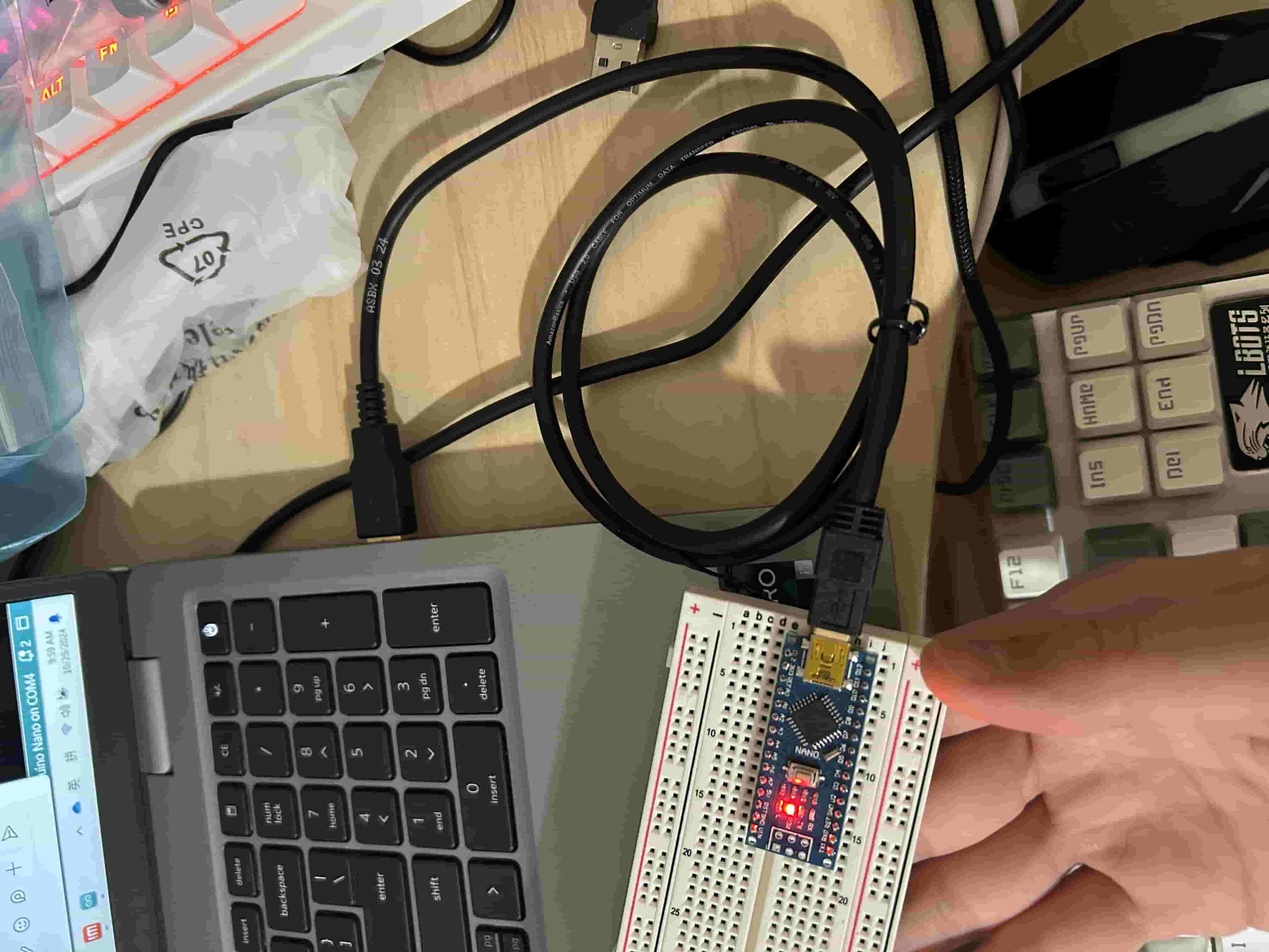
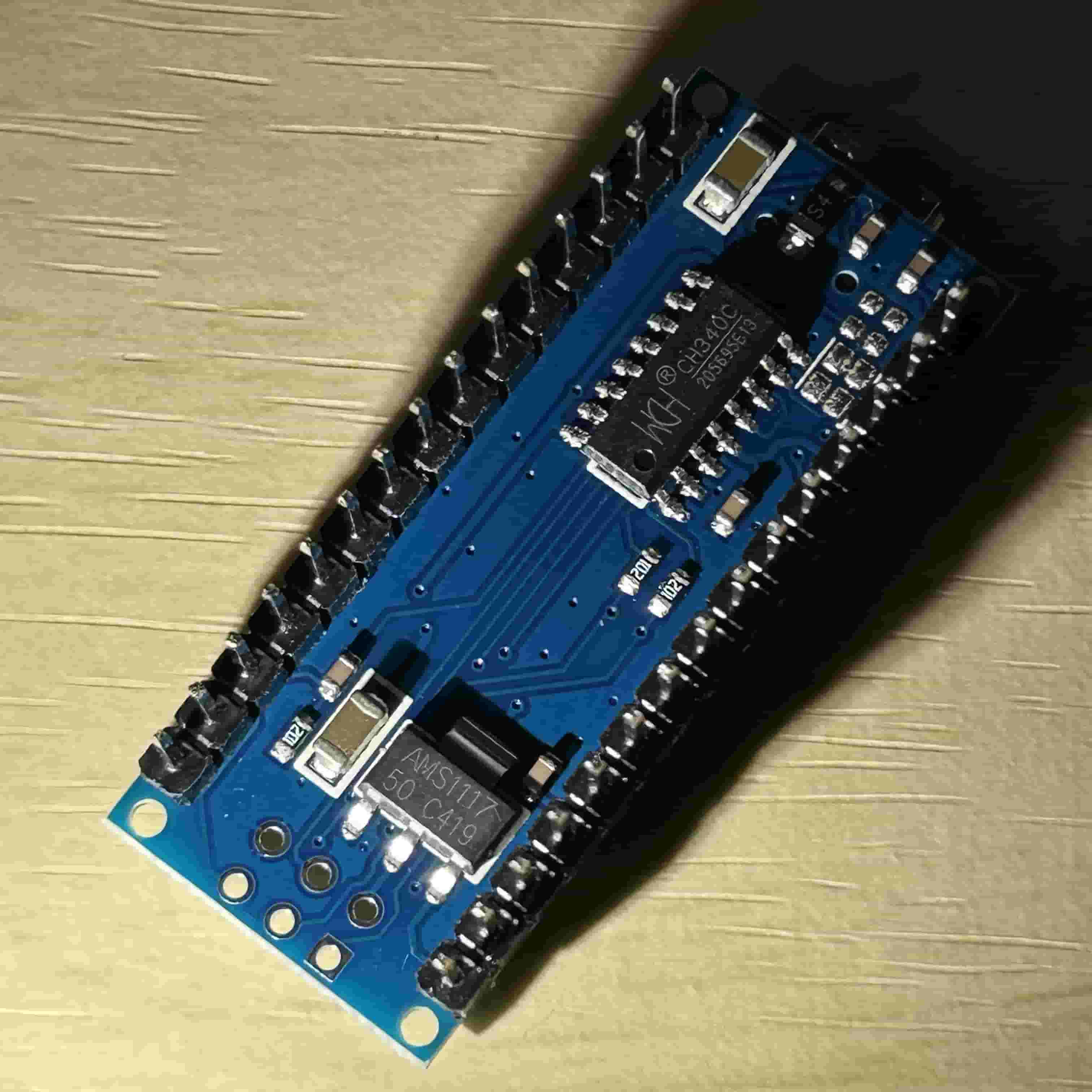
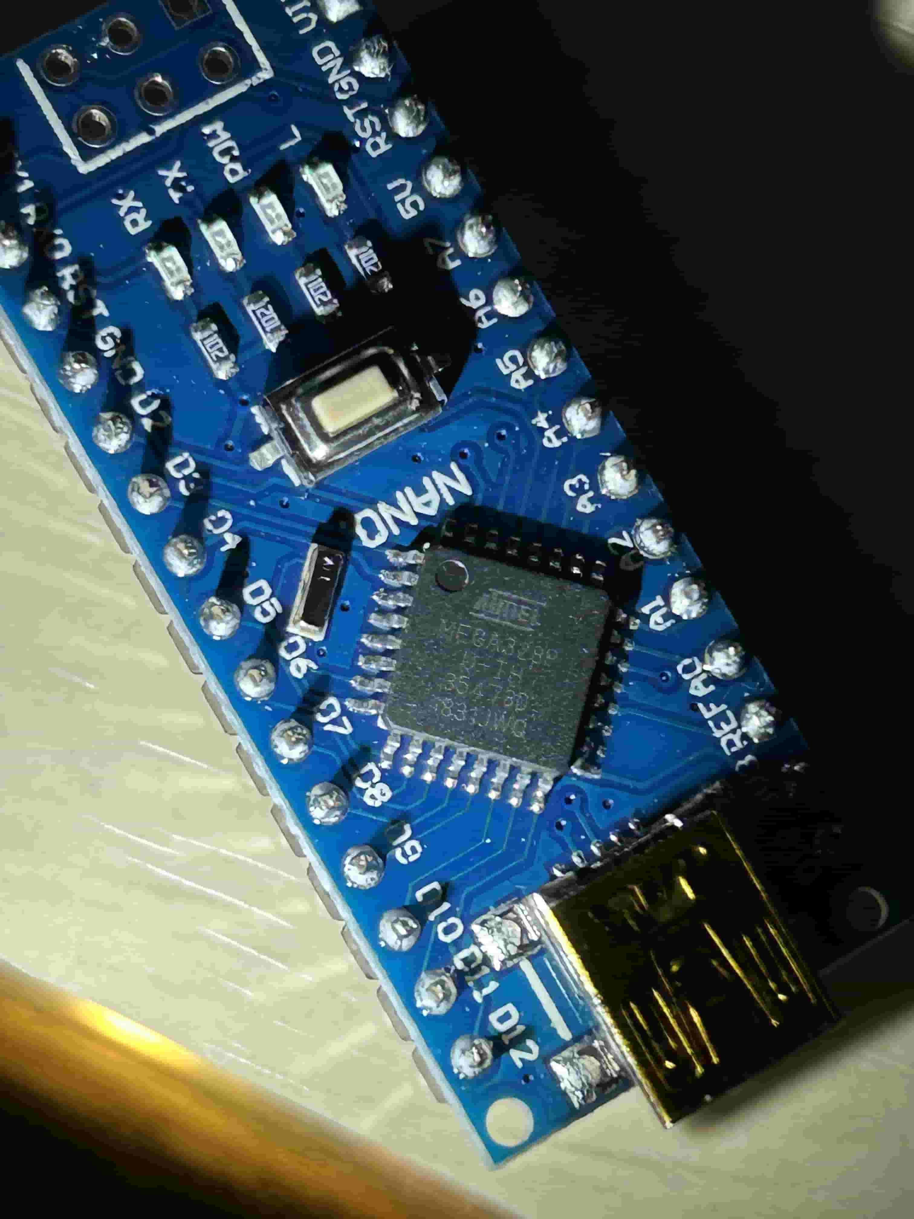
Blink Nano
Can’t Upload
References:
-
电子教学 - 【教学】Arduino上传失败的24种解决方法 - bilibili - joyspace
- Searched by
Arduino烧录失败in bilibili
- Searched by
-
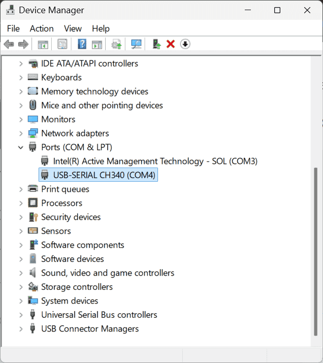
avrdude: ser_open (): can’t open device “\.\COM4”: acces denied
- Searched by
avrdude: ser_open(): can't open device "\\.\COM4": Access is denied.in DDG
- Searched by
-
CH340 Windows 10 driver download | arduined.eu
- Searched by
Arduino Nano CH340in DDG
- Searched by
-
Uploading a simple sketch takes forever - arduino uno - SE
- Searched by
arduino IDE uploading long timein DDG
- Searched by
(2024-10-29)
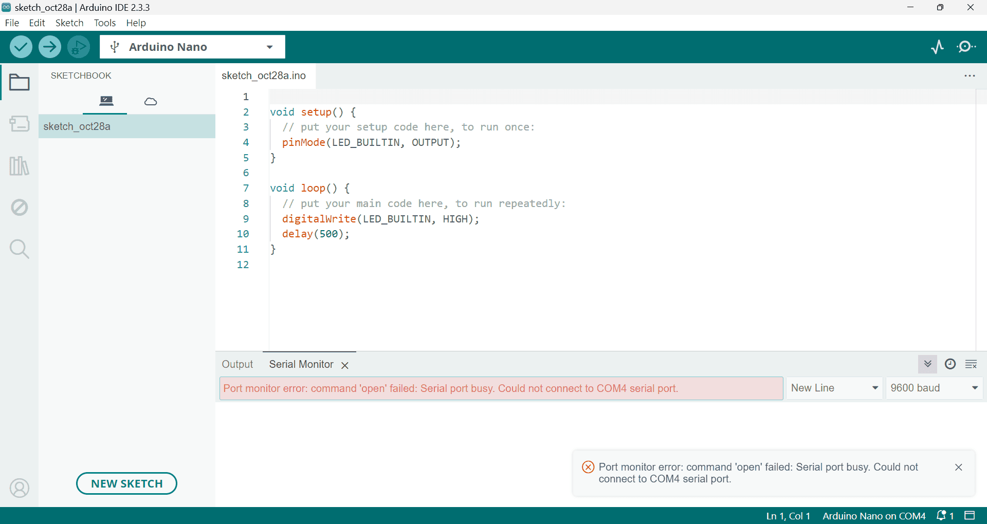
Problem: Cannot upload firmware to board: Arduino Nano
-
Hardware connection: Plug USB cable barely between the Nano board and laptop.
-
Board and Channel selection:

-
My own sketch cannot be uploaded to board.
The “Uploading” reminder hangs forever, and finally the following errors prompted:
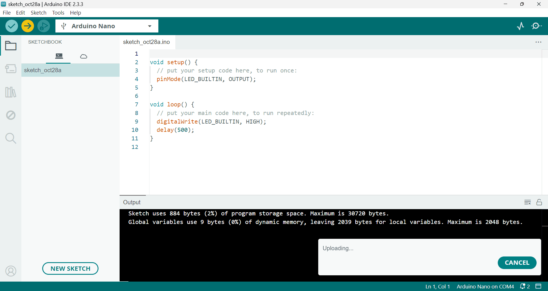
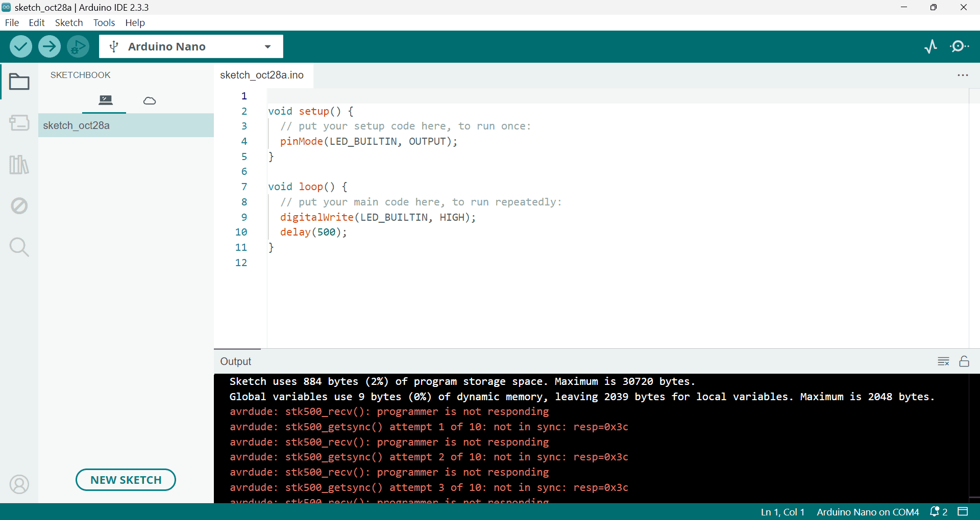
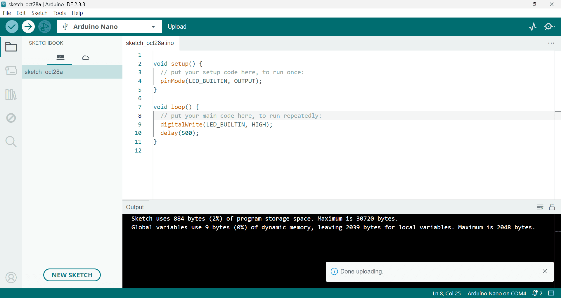
1
2
3
4
5
6
7
8
9
Sketch uses 924 bytes (3%) of program storage space. Maximum is 30720 bytes. Global variables use 9 bytes (0%) of dynamic memory, leaving 2039 bytes for local variables. Maximum is 2048 bytes. avrdude: stk500_recv(): programmer is not responding avrdude: stk500_getsync() attempt 1 of 10: not in sync: resp=0xaa avrdude: stk500_recv(): programmer is not responding avrdude: stk500_getsync() attempt 2 of 10: not in sync: resp=0xaa ... # repeated messages avrdude: stk500_recv(): programmer is not responding avrdude: stk500_getsync() attempt 10 of 10: not in sync: resp=0xaa -
The official example (‘File’ -> ‘Examples’ -> ‘01.Basics’ -> ‘Blink’) cannot be uploaded either
1avrdude: ser_open(): can't open device "\\.\COM4": Access is denied. -
‘Serial Plotter’ and ‘Serial Monitor’ both don’t return anything. Sometimes, it showed ‘Not connected. Select a board and a port to connect automatically.’.
Adressing
-
Install driver for CH340 chip.
-
Reasons
-
Actions:
-
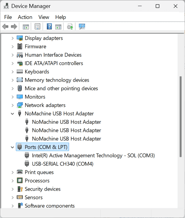
I checked the driver in ‘Device Manager’ before installation (r3-eu), and found it had been installed:
-
-
Results:
- I didn’t install the driver right away, becaues I also noticed NoMachine (remote desktop) also use USB.
-
Analysis: Maybe the NoMachine occupies some resources?
-
-
Close the remote connection of NoMachine.
- Results:
- After relaunching the Arduino IDE, the ‘Uplong’ still can’t complete.
- Results:
-
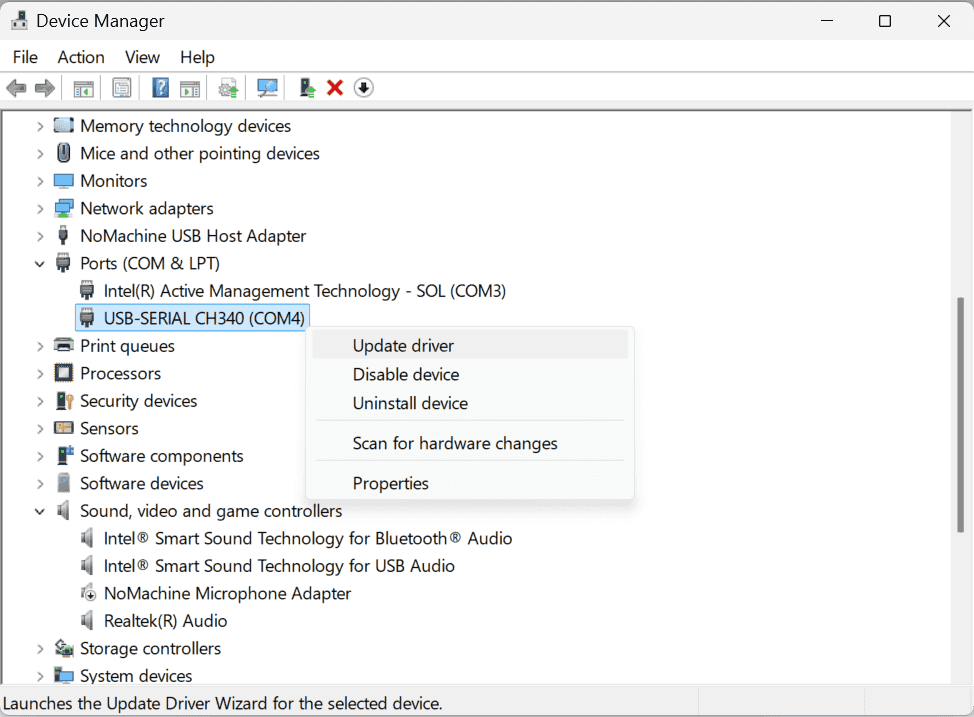
Try to Update the driver, as suggested by (r3-eu)
-
Actions:
-
Click “Update”
-
-
Results:
-
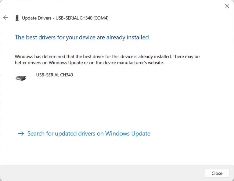
It’s already installed:
-
-
-
Install the driver again by using
CH341SER\SETUP.EXE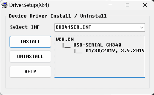
-
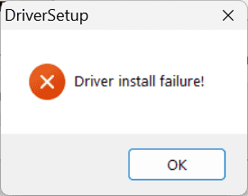
Results:
-
Failed:
-
-
-
Quit NoMachine first, then install SETUP.EXE:
-
Actions:
- Quit NoMachine service:
Tray menu Confirm quit 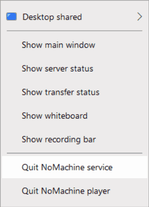
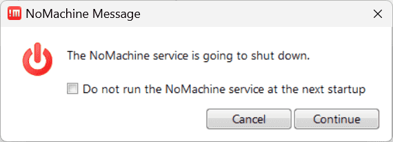
- Quit NoMachine service:
-
Results:
- Driver installation still failed.
-
-
Uninstall NoMachine and restart the laptop.
-
Actions:
-
Check the ports. There is only one port:
COM3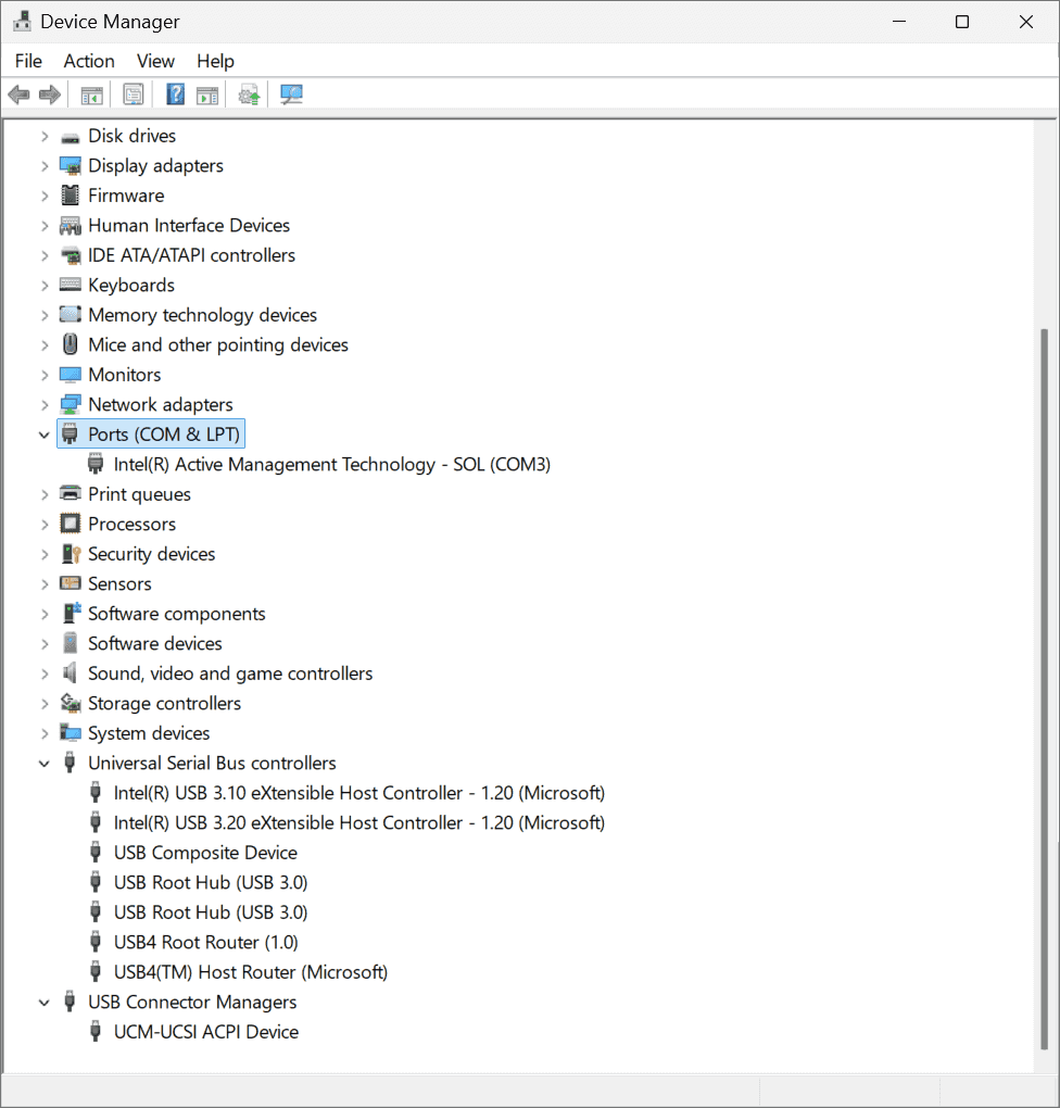
-
-
Results:
- Cannot upload the firmware.
-
-
Plug the cable into the other USB slot, whose index is COM5:
-
Actions:
-
Plug into another USB
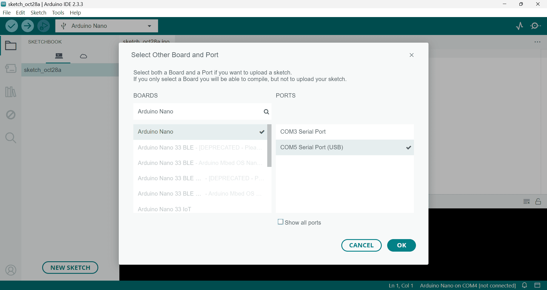
-
-
Results:
- Doesn’t work either.
-
-
Reinstall the driver SETUP.EXE,
-
Results:
1.No luck: “Driver install failure!” persists.
-
-
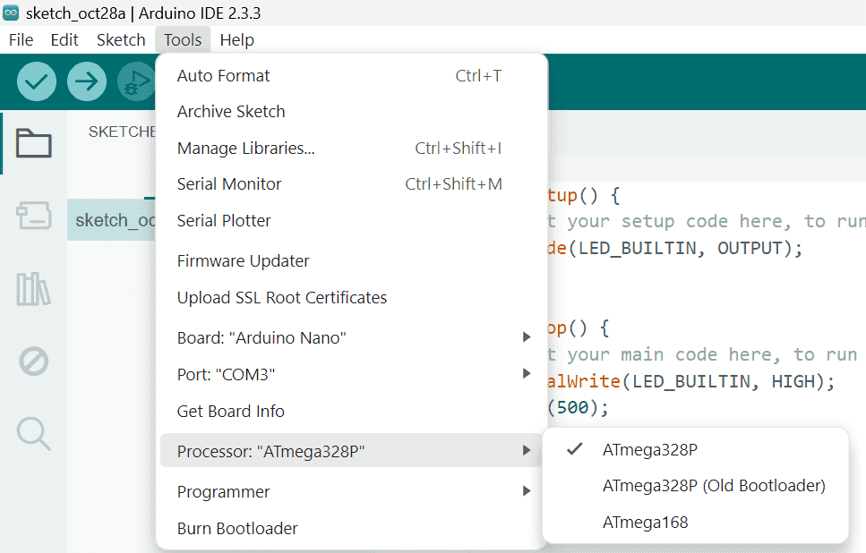
Select another processor:
ATmega328P (Old Bootloader)instead ofATmega328P-
Reasons:
-
Glipsed an answer that mentioned to use the old version (r4-SE)
-
The combination of my previous trials is:
-
-
Results:
-
It works!
-
The driver apperas again automatically, though I didn’t install it manually.
-
-
Conclusion:
- The problem is not the CH340 driver, but the processor.
-
LED Chaser
References:
-
Arduino基础课程01——初始Arduino - bilibili - funcodecc
- Directed by Arduino基础课程09——SPI通信
-
Arduino Tutorial: LED Sequential Control- Beginner Project - YouTube - Drone How
- Searched by
arduino experiments flowing ledin Google video
- Searched by
Materials:
-
Recite the code after the first watch:
 1
 2
 3
 4
 5
 6
 7
 8
 9
10
11
12
13
14
15
16
17
18
19
20
21
22
23
24
25
26
27
28
29
void setup() { pinLed[] = {1,2,3,4}; // Indices of pins to be used numLed = 4 // Configure pins // Specify Mode for pins: INPUT or OUTPUT // Set every pin to OUTPUT to drive an LED for {i=1, i<=numLed, i++} { pinMode(pinLed[i], 'OUTPUT'); // Input 2 args: pin id and mode } } void loop() { for{i=0; i<=numLed; i++} { digitalWrite(pinLed[i], HIGH); // Two levels of voltages delay(500); // ms digitalWrite(pinLed[i], LOW); } for{i=numLed, i>0; i--} { digitalWrite(pinLed[i], HIGH); delay(500); digitalWrite(pinLed[i], LOW) } }My Mistakes:
-
OUTPUTas a pinMode seems to be a global variable, NOT a string. -
Data types are missed when create a variable:
int numLed = 4. -
The pin-1 of UNO cannot be set as
OUTPUT? The pins used are started from pin-2:int pinLed[] = [2,3,4,5] -
The arguments of syntax
forare separated by;and enclosed by parentheses( ), not curly braces. And the temporary counterialso needs declaration of data type. -
iis the index of the array, ranging from 0-3. -
Don’t forget semicolons at the end of each line;
-
Variables used both by
setup()andloop(), i.e.,numLedandpinLedshould be declared outside of these functions. -
Don’t forget current-limit resistor. There is a warning from the simulation platform (funcode.cc): “The maximum current allowed by led-node is: 0.02”
-
-
Rectified code for Arduino Nano:
 1
 2
 3
 4
 5
 6
 7
 8
 9
10
11
12
13
14
15
16
17
18
19
20
21
22
23
24
int pinLed[] = {10,11,12,13}; int numLed = 4; void setup(){ // Set the mode of each pin to OUTPUT for(int i=0; i<=numLed; i++){ pinMode(pinLed[i], OUTPUT); } } void loop(){ // From pin-2 to pin-5 for(int i=0; i<=numLed; i++){ digitalWrite(pinLed[i], HIGH); delay(500); digitalWrite(pinLed[i], LOW); } // From pin-5 to pin-2 for(int i=numLed-1; i>=0; i--){ digitalWrite(pinLed[i], HIGH); delay(500); digitalWrite(pinLed[i], LOW); } }
- Mount components onto breadboard, and upload the firmware to board.
Circuit Demostration 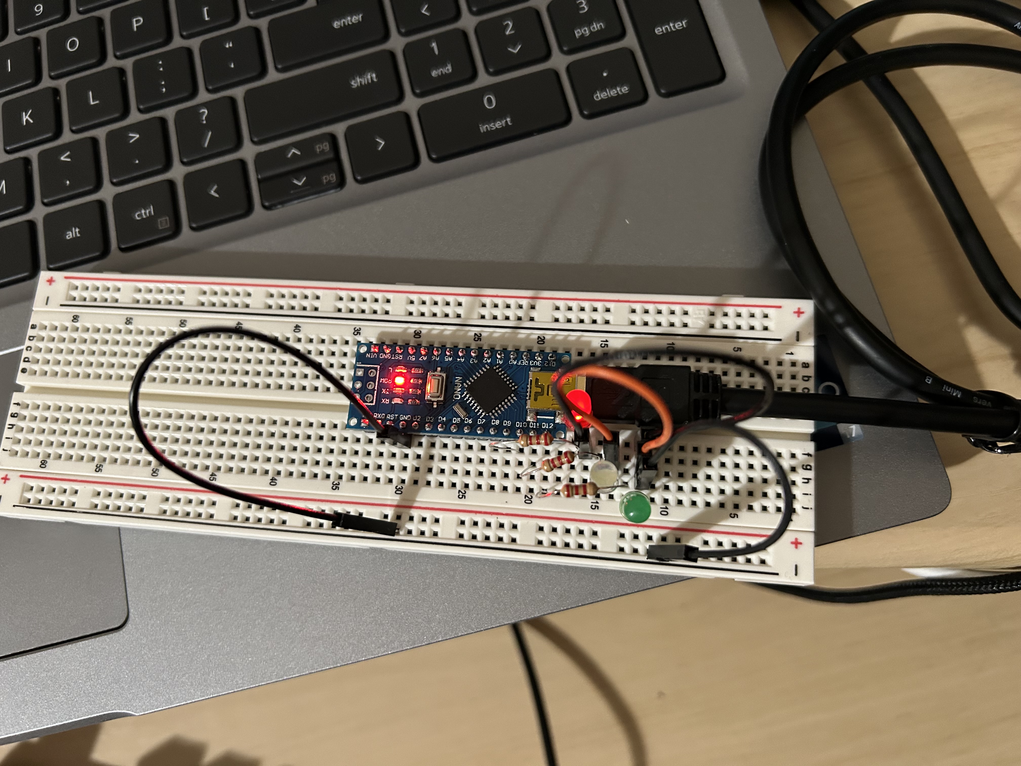
 https://i.ibb.co/PCqxrB6/Ardu-Test-Blink-Nano-Breadboard-2024-10-29-115901.gif
-
Practice:
Use two pins: #2 and #3 to light two LEDs alternatively. Each LED is on for 0.5 seconds and off for 0.5 seconds.
Code:
- Use
forto configure each pin
 1
 2
 3
 4
 5
 6
 7
 8
 9
10
11
12
13
14
15
16
17
int pinLed[] = {2,3}; int numLeds = 2; void setup() { for(int i=0; i<numLeds; i++){ pinMode(pinLed[i], OUTPUT); } } void loop() { for(int i=0; i<numLeds; i++){ digitalWrite(pinLed[i], HIGH); delay(500); digitalWrite(pinLed[i], LOW); delay(500); } }Simulation platform: funcode.cc

- Use
Piezo
Simulation
References:
- Detect a Knock - Arduino Docs
-
Piezo sensor with Arduino UNO - How does work Piezo sensor (Code and Circuit Diagram) - YouTube - uSriTu Hobby
- Searched by
Piezo electric disc experiments with Arduinoin DDG video
- Searched by
-
Arduino Workshop-Piezo Knock Sensor - Hackster.io
- Found in s2
Materials:
(2024-10-25)
- Simulation platform:
SPI LED Array
References:
- MajicDesigns/MD_Parola
- Was looking for examples directly using the generic library
<SPI.h>instead of calling sensor-specific library. Although Wokwi supports some devices, most of them uses derived libraries. - I found wokwi-max7219-matrix Dot Matrix Reference - Wokwi Docs when browsing the Docs of Supported Hardware -> Diagram Reference.
- One of its ‘Simulator examples’ is Dot Matrix Clock,
which writes
#include <SPI.h>explicitly.
- Was looking for examples directly using the generic library
Notes:
(2024-10-31)
- A library controlling LED array using SPI interface.
Serial
References:
- Arduino基础课程07——串行通信 - bilibili - funcodecc
-
Universal Asynchronous Receiver-Transmitter (UART) | Arduino Documentation
- Searched by
Arduino sends and receives character via UARTin DDG
- Searched by
-
serial - ‘Serial1’ was not declared in this scope - Arduino Stack Exchange
- Searched by
Arduino Serial exit status 1 Compilation error: 'Serial1' was not declared in this scopein DDG
- Searched by
-
‘Serial1’ was not declared in this scope - Arduino Forum
- Found in s3
-
Adding More Serial Ports to your board. - Arduino Docs
- Refered by r3-SE
-
Arduino项目实战_第四课_串口通信_(3)软串口与双机通信_哔哩哔哩_bilibili - 电子疯狂创客
- Searched by
Arduino nano 串口实验 site:bilibili.comin DDG
- Searched by
Notes:
-
Just connect the Nano board with laptop with a USB cable, then upload the code (r1-Bili):
1
2
3
4
5
6
7
8
void setup() { Serial.begin(9600); } void loop() { Serial.println("Hello"); delay(1000); }
(2024-11-29)
-
Serial1doesn’t exist on Nano or Uno. Nano only has one serial port, calledSerial.-
I think this
Serialis not only connected to pins:TX1andRX0, but also the USB port. -
Nano has NO pins for
Serial1r4-Forum,r2-DocsHowever, it can be instantiated with the
SoftwareSeriallibrary r3-SE toextend the RX and TX tosimulate another serial port on other pins r5-Tutorial:1 2 3 4 5 6 7 8#include <SoftwareSerial.h> SoftwareSerial Serial1(3,2); //Rx to pin D3, Tx to pin D2 void setup() { Serial.begin(9600); // Initialize the Serial monitor for debugging Serial1.begin(9600); // Initialize Serial1 for sending data }
-
(2024-12-05)
-
The SoftwareSerial is an individual serial port, which can do the complete serial function by iteself.
-
Reasons:
-
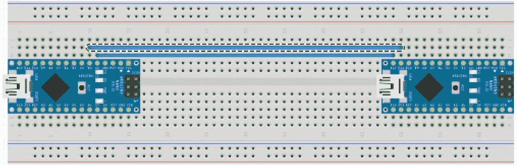
Do not mix up the pins of the generic serial (TX1 & RX0). The following image shows two boards are connected with their SoftwareSerial r6-bili:
-
Serial.print()will send (wirite) data to the bus.
-
-
Actions:
1 2 3 4 5 6 7 8 9 10 11 12 13 14 15 16 17 18 19 20 21 22 23 24 25 26 27 28 29 30 31 32#include <SoftwareSerial.h> SoftwareSerial Sserial1(3,2); // RX, TX String str; char c; void setup() { Sserial1.begin(9600); Serial.begin(9600); } void loop() { /* Check the buffer of the SoftwareSerial */ while (Sserial1.available()) { c = Sserial1.read(); /* read 1 byte */ str +=c; if (c == '\n') { /* Use original serial to sent to PC */ Serial.print(str); str = ""; /* Reset str */ } } /* Use the SoftwareSerial to transmit str */ while (Serial.available()) { c = Serial.read(); // Recv str from PC str += c; if (c == '\n') { // Ended with newline /* Use SoftwareSerial to sent to other dev */ Sserial1.print(str); str = ""; } } } -
Results:
- The code in Arduino Docs is equivalent besides the additional SoftwareSerial usage.
-
Pinout
References:
-
PIN number to use with arduino nano - Arduino Forum
- Searched by
arduino nano pin numbersin DDG
- Searched by
Notes:
-
A pin should be referred to in the program by the number in its name.
-
Although the
D1andA1have the same “number” 1, but they are gotten controlled with two totally different functions:digitalWrite()andanalogWrite().The name
D13means the digital pin-13. The combination of a number plus a functiondigitalWrite/analogWriteis unique; there is no confusion.1 2 3int pinLed = 13; pinMode(pinLed, OUTPUT); digitalWrite(pinLed, LOW);- Do not get confused by other images labeling “pin number”, which are only for breadboard (r1-Forum), such as this image for “Nano Every”.
For the
SSpin, I should look up forD10pin on the board and usedigitalWrite()to control it:1 2 3int ssPin = 10; pinMode(ssPin, OUTPUT); digitalWrite(ssPin, LOW);
-