Table of contents
(Feature image from RTK7F124FPC01000BJ - RL78/F24 (R7F124FPJ) Target Board | Renesas )
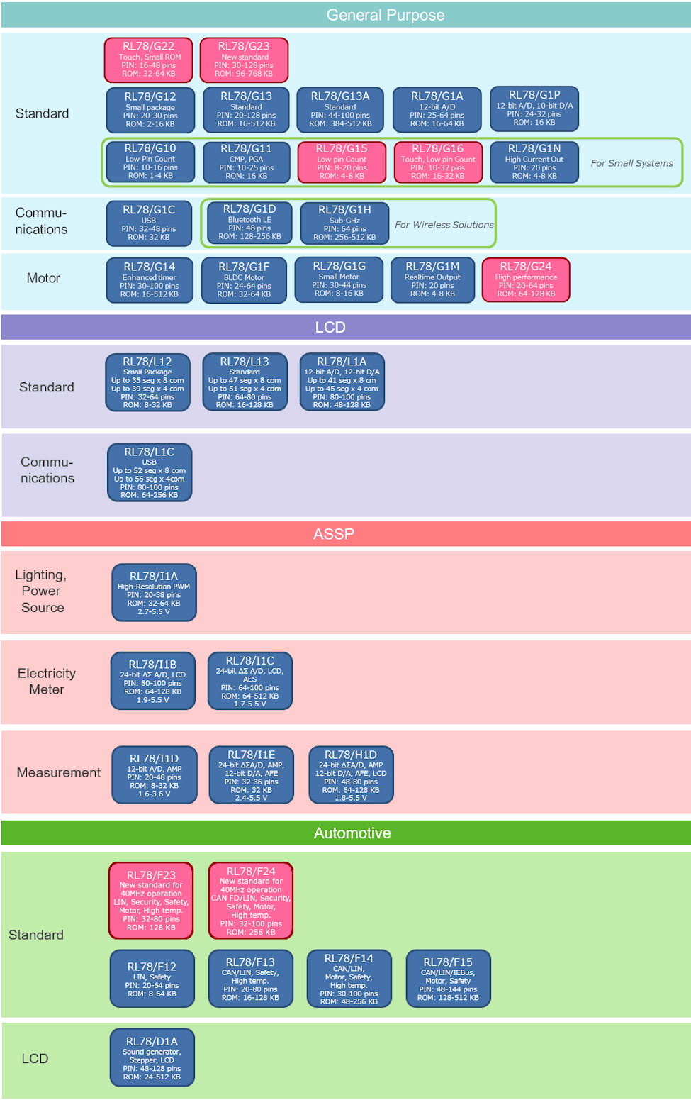
RL78 Family
References:
-
RL78 Series - Low-Power 8-Bit & 16-Bit Microcontrollers (MCU) | Renesas
- Searched by
RL78 F24 Flash Ledin DDG
- Searched by
-
RL78/F23, F24 RENESAS MCU
- Collected in RL78 Low Power 16-bit MCUs for Automotive | Renesas
- Searched in s1
Notes:
-
Brief comparision among MCUs r1-MCU:
-
RL78/F24 (R7F124FPJ 100-pin) block diagram shows the
UART0(RXD0andTXD0) is inside theSAU0r2-F24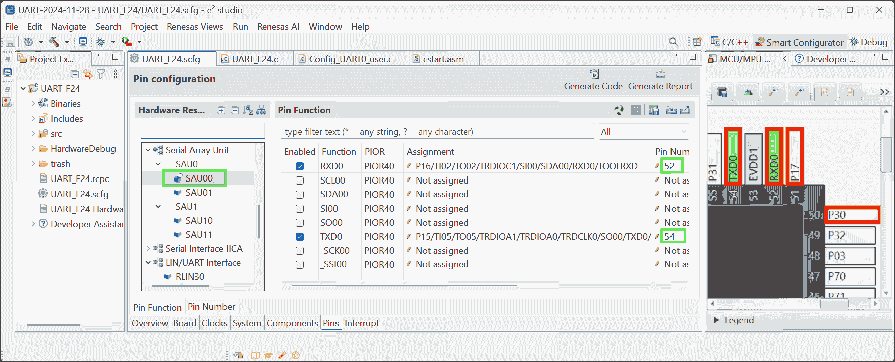
UART
Hardware
References:
-
Implementing UART Tx in RL78 F14 - YouTube - SM training academy
- Searched by
UART code demonstration for Renesas RL78/F23in DDG video
- Searched by
-
RTK7F124FPC01000BJ - RL78/F24 (R7F124FPJ) Target Board | Renesas
- Searched by
renesas R7F124FPJ3A downloaderin DDG
- Searched by
-
E2 Emulator Lite RTE0T0002LKCE00000R User’s Manual
- Searched by
Renesas E2 lite usagein DDG
- Searched by
-
- Searched by
- Searched by
Environment:
-
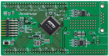
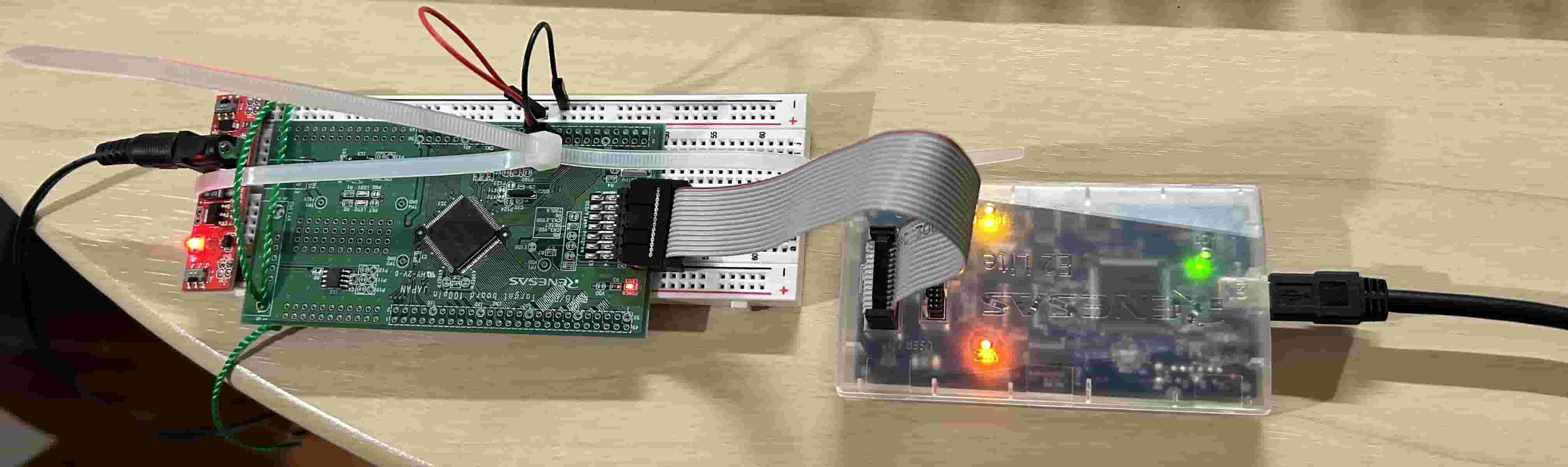
RL78 / F24 Target board 100 pin
- MCU:
R7F124FPJ3A, 2335AM456 - PCB: RTK7F124FPC01000BJ REV.1.0
- MCU:
-
E2 Emulator Lite: RTE0T0002LKCE00000R
Notes:
(2024-11-25)
-
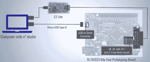
The TTL needs to be converted to USB voltage level to achieve the communication between a PC and a UART r1-SM.
-
However, I don’t have a convertor.
-
I have an Arduino Nano, which can be connected to a USB (
COM) port.
-
-
I don’t Short circuit pins as RL78/G23 required? r2-Intro in the video r1-Show.
-
I just connected the
VDDpin (#20 in the connector CN1) to 3.3V, and theGND(#22 in CN1) to ground.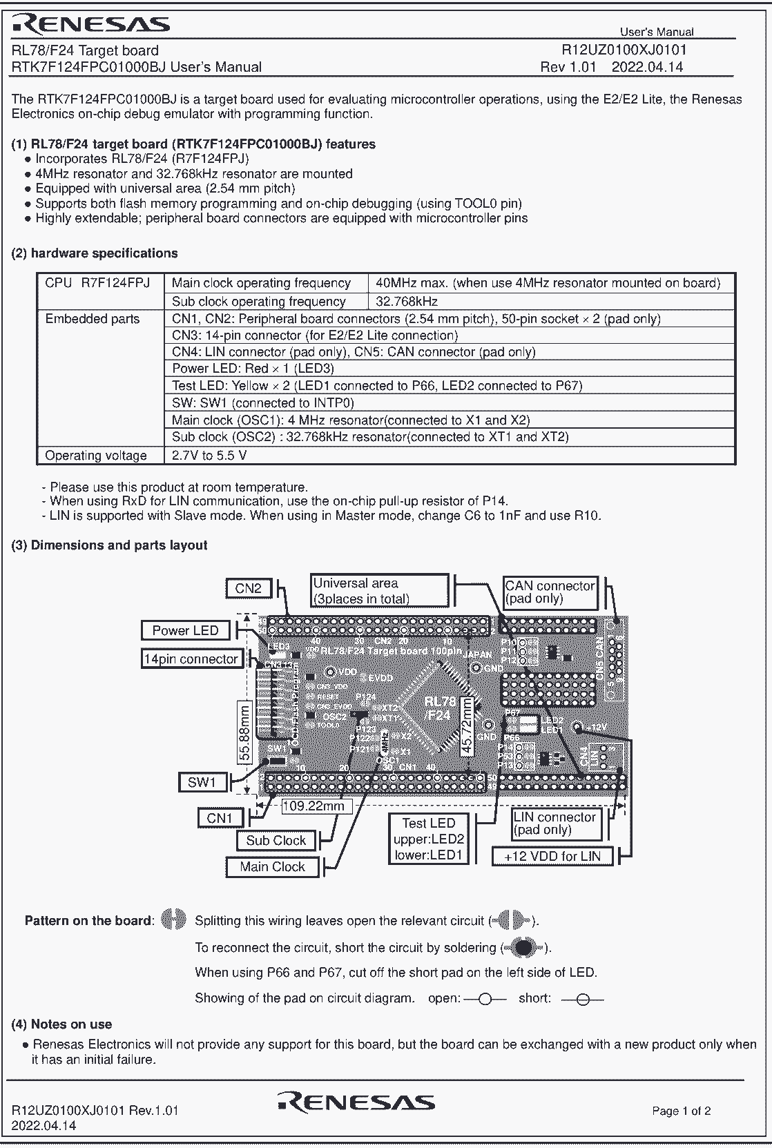
-
Smcg Uart
References:
-
How to Create a UART Communication Project Using Smart Configurator in e² studio
- Collected by RL78 Smart Configurator | Renesas
- Searched by
smart configurator for RL78 F23 UARTin DDG
-
RL78 Smart Configurator User’s Guide: IAREW
- Collected by RL78/F24 Guide for Engineer - Renesas Electronics Corporation
- Searched by
UART Communication component on RL78/F24in DDG
-
- Searched by
- Searched by
Notes:
(2024-11-26)
-
Creat a new Smcg project:
-
Select device:
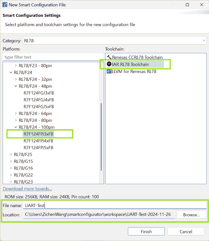
-
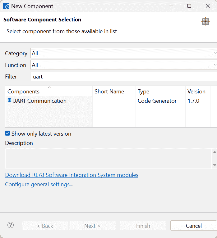
Add UART component and specify operation:
-
The resource can be
RLIN30orRLIN31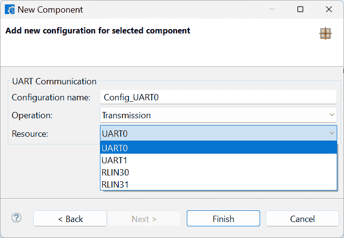
-
-
-
The file structure of code generated by Smcg r2-Docs
Modify Code
References:
-
Smart Configurator User’s Manual: RL78 API Reference
- Listed in the Documentation: RL78 Smart Configurator | Renesas
Notes:
(2024-11-25)
-
The
r_cg_serial.hlists all the functions can be used in the UART communication r1-16:07.-
That means I may need to be familiar with the usage of each function r1-Manual.
-
Basically, 2 functions are most often used:
1
2
3
void R_UART0_Start(void); MD_STATUS R_UART0_Send(uint8_t* const tx_buf, uint16_t tx_num); -
A callback function
r_uart0_callback_sendend(void)(defined inr_cg_serial_user.c) will be executed after the transmission completed. r1-33:48
-
IAREW
Build Error
References:
Problems:
-
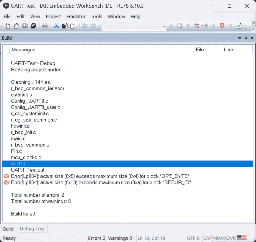
I copied the code from video r1-YouTube, then clicked the
Build Allin IAR. The building failed. -
Two errors that some sizes (of sections) exceed the block size
OPT_BYTEandSECUR_IDBuild Error:
Error Messages
 1
 2
 3
 4
 5
 6
 7
 8
 9
10
11
12
13
14
15
16
17
18
19
20
21
22
23
24
25
26
27
Messages UART-Test-Debug Reading project nodes ... Cleaning ... 14 files. r_bsp_common_iar.asm cstartup.s Config_UARTO.c Config_UARTO_user.c r_cg_systeminit.c r_cg_sau_common.c hdwinit.c r_bsp_init.c main.c r_bsp_common.c Pin.c mcu_clocks.c vecttbl.c UART-Test.out Error[Lp004]: actual size (0x5) exceeds maximum size (0x4) for block "OPT_BYTE" Error[Lp004]: actual size (0x10) exceeds maximum size (0xa) for block "SECUR_ID" Total number of errors: 2 Total number of warnings: 0 Build failed
Notes:
E2 Studio
References:
-
E2 Emulator Lite RTE0T0002LKCE00000R User’s Manual
- Searched by
Renesas E2 lite usagein DDG
- Searched by
Notes:
(2024-11-28)
-
Hardware Resources
-
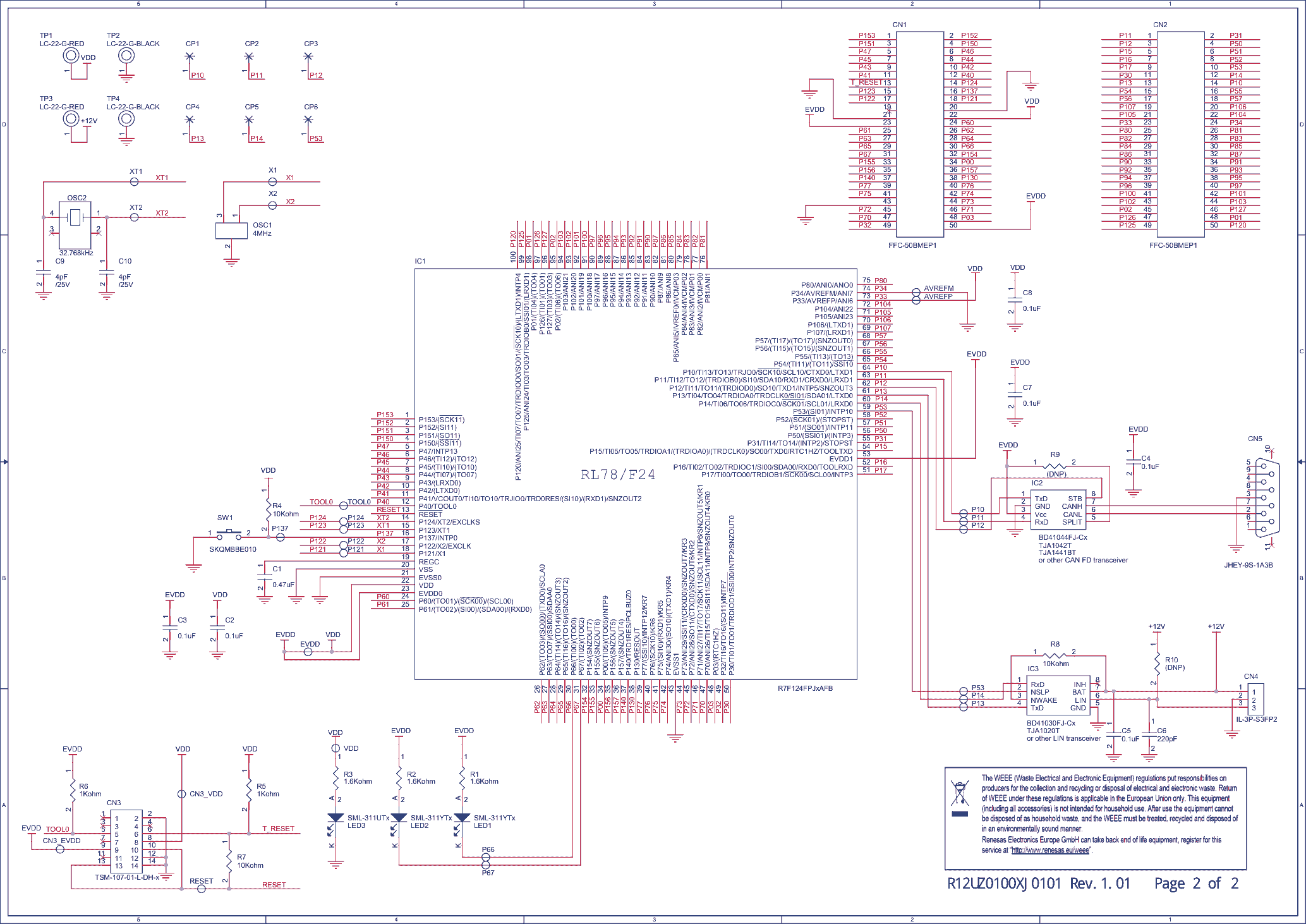
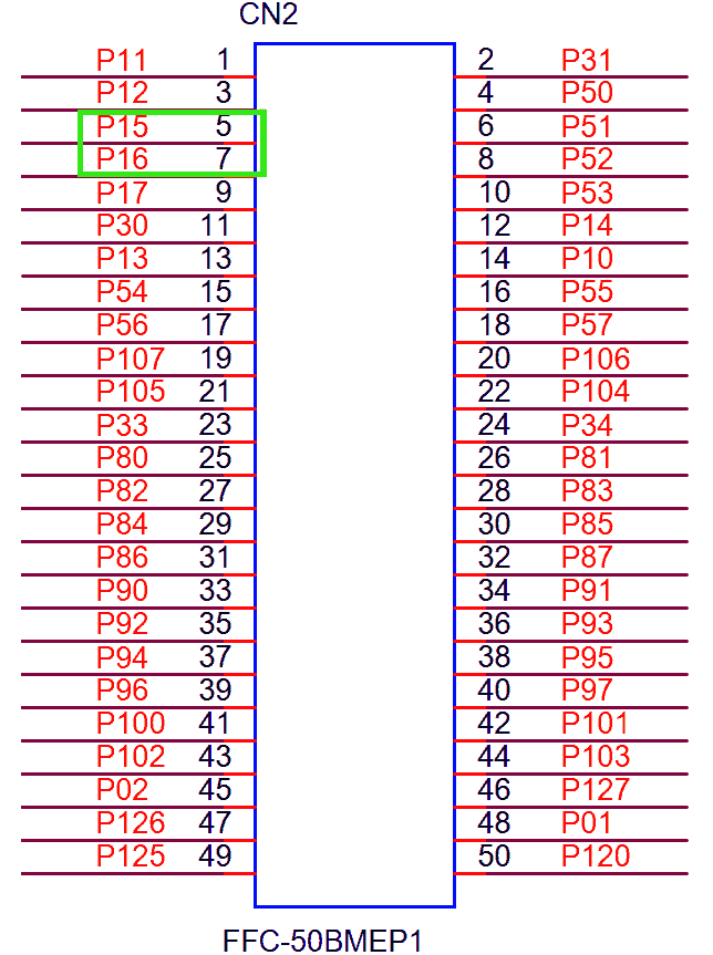
Pins of
TXD0(Pin:P15) andRXD0(Pin:P16) on the target board: Connector2 - pin#5 (TXD0) and pin#7 (RXD0).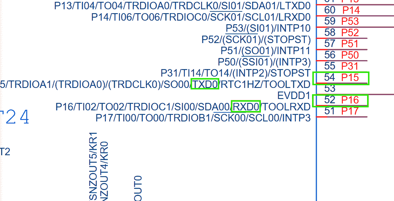
-
-
Configure The Components
-
Create an E2 Studio project
-
Configure
UART Communication: Transmission and Reception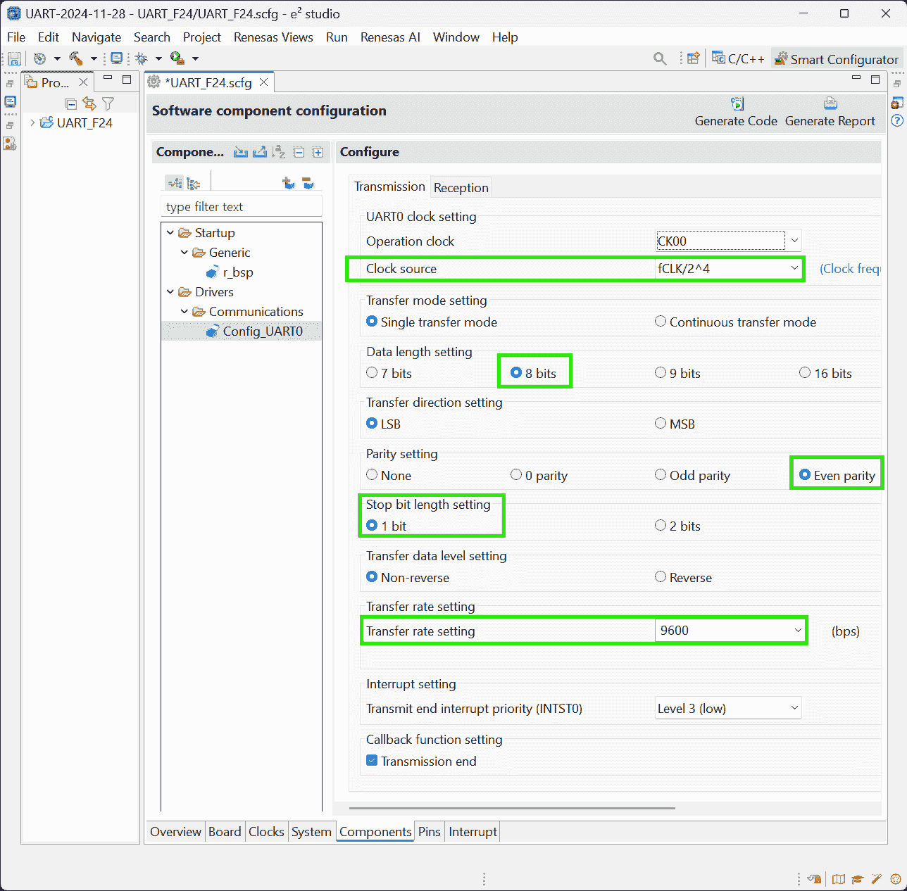
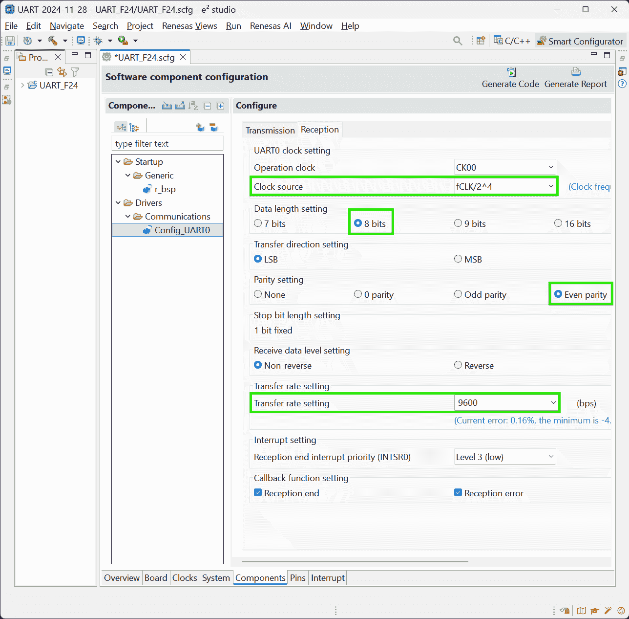
-
-
Add User Code And Run The Project
-
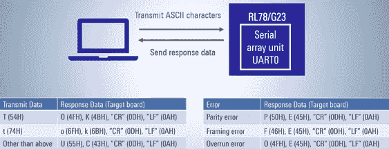
UART_F24.c: Define reception buffer and messages to be sent outside themainfunction as global variables1 2 3 4 5 6 7 8 9 10 11 12/** Global variables and functions (to be accessed by other files) */ uint8_t g_Uart0RxBuf; /* UART0 receive buffer */ uint8_t g_Uart0RxErr; /* UART0 receive error status */ MD_STATUS g_Uart0TxEnd; /* UART0 transmission end */ /** Private global variables and functions (to be sent) */ static uint8_t messageOK[4] = {"OK\r\n"}; /* Message for receiving "T" */ static uint8_t messageok[4] = {"ok\r\n"}; /* Message for receiving "t" */ static uint8_t messageUC[4] = {"UC\r\n"}; /* Message for receiving other characters */ static uint8_t messageFE[4] = {"FE\r\n"}; /* Framing error message */ static uint8_t messagePE[4] = {"PE\r\n"}; /* Parity error message */ static uint8_t messageOE[4] = {"OE\r\n"}; /* Overrun error message */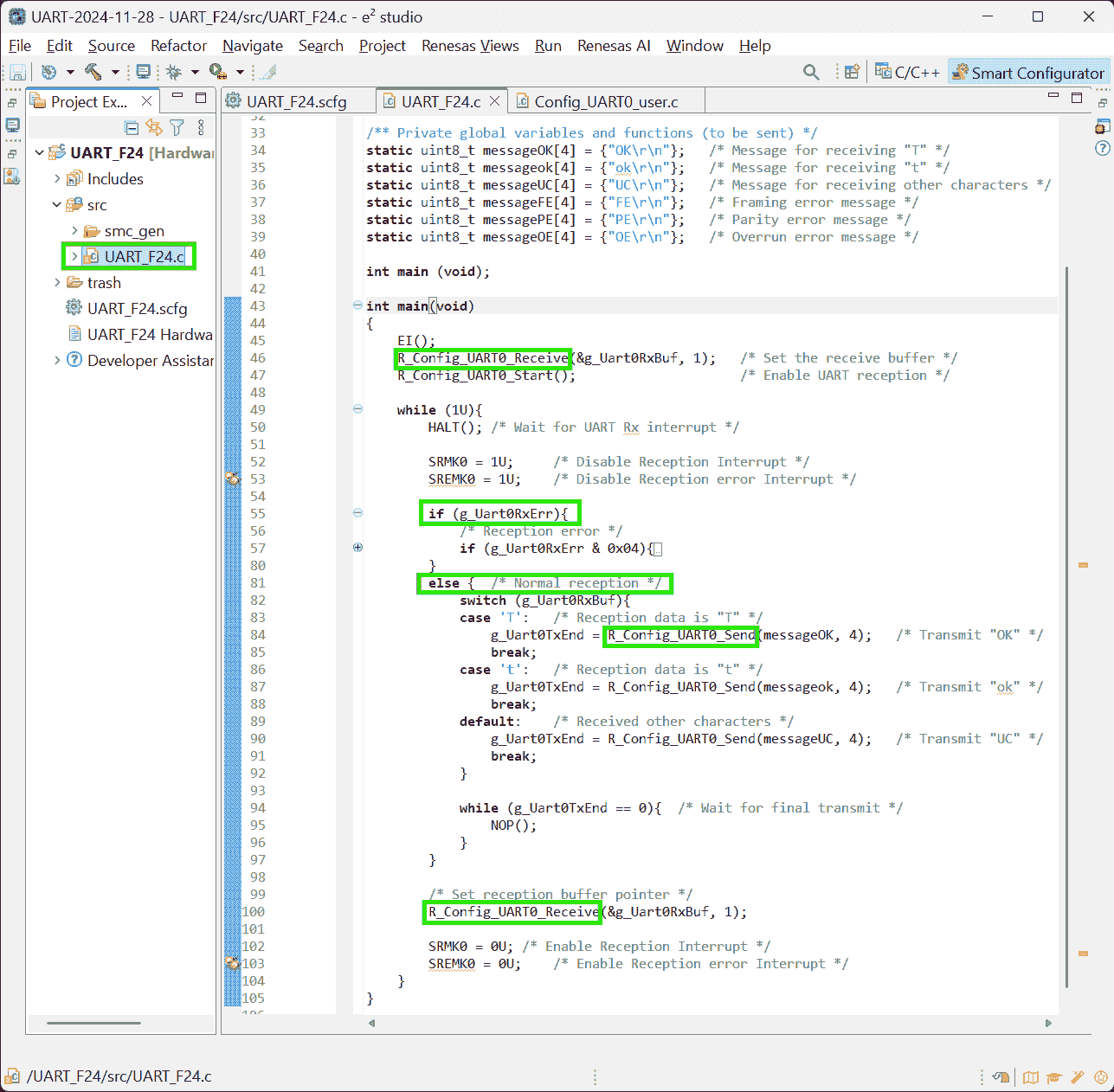
-
Config_UART0_user.c: Customized callback functions (triggered by respective interruption)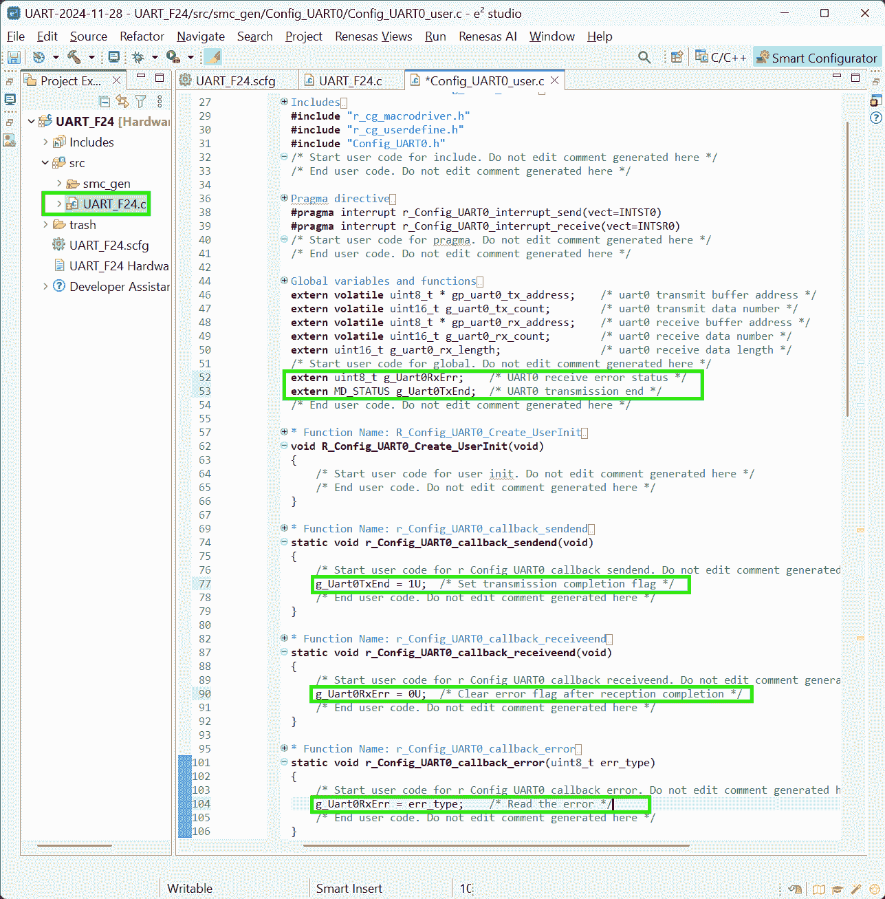
-
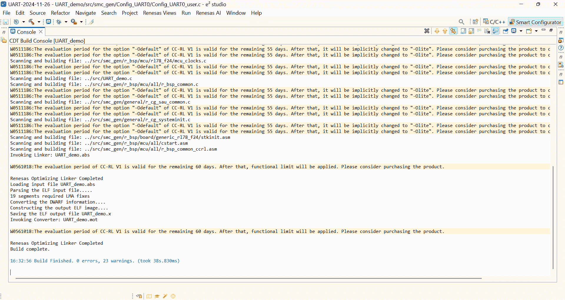
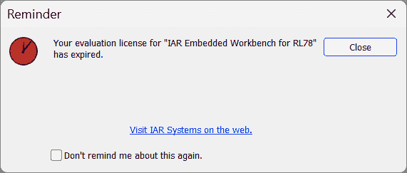
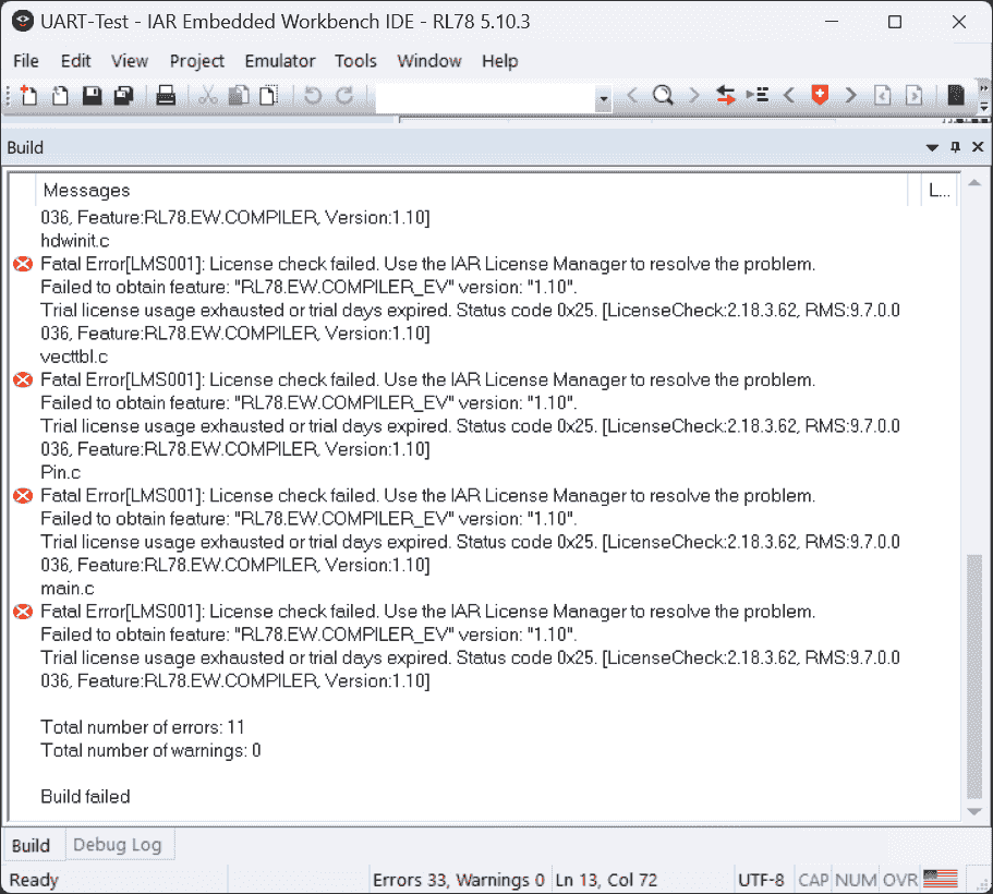
The same code can be built with 0 error, but prompting liscene warning:
-
Analysis:
-
Maybe IAR’s liscene has been expired. So, the program cannot be built correctly.
- Today should be the last of my evaluation liscene, as the prompt shows “will be expired in 0 days”.
(2024-11-27)
-
Nov 27 becomes red:
-
-
-
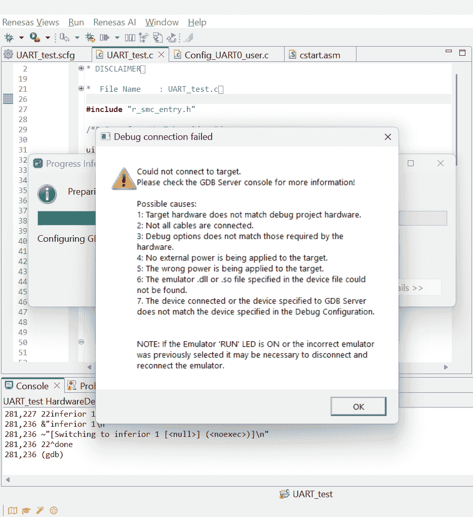
E2 studio cannot debug: Must connect to the debugger
-
E2 studio cannot debug: Do not power the board when debugging with a debugger. r1-Manual
ICD Debugger
(2025-01-04)
-
Connect tag of Microchip ICD (In-Circuit Debugger) to 14-pin cable of E2 Lite:
E2 Lite Programmer 14 pin Tag Connect 6 pin Pin 2 Pin 4 – GND Pin 5 Pin 5 – Tool0 Pin 8 + 9 Pin 2 – VCC Pin 13 + 10 Pin 1 - MCU RST - Reference: EE_Team > Hardware > E41 > E41 Programmer to ECU.docx
Upload
Problems:
-
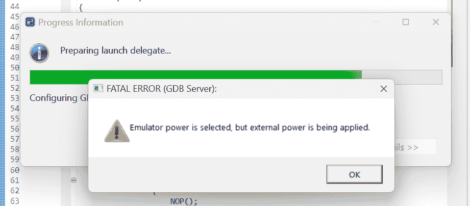
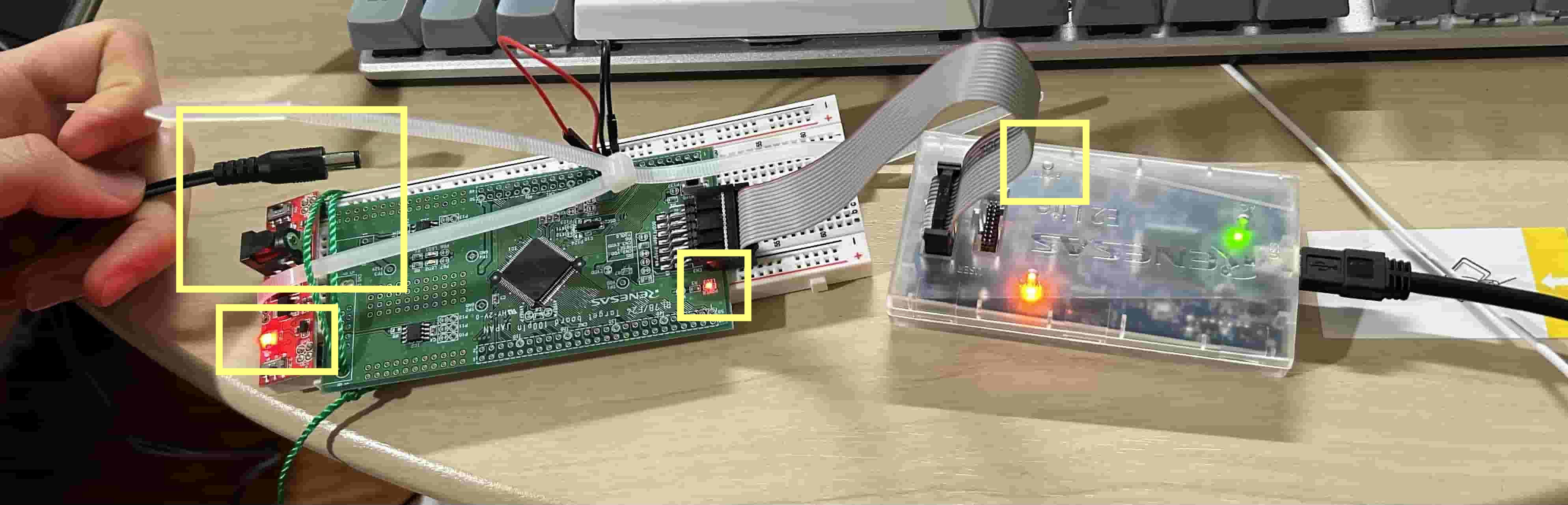
I don’t want to test the code by launching “Debug” every time. I want to embed the program into the MCU and let it run itself after power on.
-
The TX and RX wires from Arduino will power the RL78 target board, and then the debugging cannot be started, as the error:
Emulator power is selected, but external power is being applied.
References:
-
Can I evaluate and develop the RL78 microcontroller on the Arduino IDE? - Renesas Electronics
- Searched by
Renesas RL78 embed a program into MCUin DDG
- Searched by
-
Serial Terminal Option in E2? - e2studio - Forum - e2studio IDE …
- Searched by
e2 studio serial monitorin DDG
- Searched by
-
e2 studio Integrated Development Environment User’s Manual: Getting …
- Found in s2
Notes:
(2024-11-29)
-
Arduino IDE can develope RL78 MCU. It supports G-class MCU r1-FAQs. I am not sure how about F24.
-
Plug in the TX and RX wires after the debugging process launched r1-Manual.
-
E2 has a serial monitor: TM Terminal r2-Forum.
-
There is a ‘Download’ button in the debugging tools r3-Manual, but mine is gray.
Pin Connection
Problems:
-
The RL78/F24 target board are connected to Arduino Nano with TX and RX wires, The Arduino will transmit the character
tto the RL78/F24. Then, the RL78/F24 is expected to returnokback. -
The Arduino Nano code is from r2-Docs. And I have extended the
RX0andTX1to pinsD3andD2
References:
-
How to read data through UART - Raspberry Pi Forums
- Searched by
raspberry pi uart receive and display on terminalin Google
- Searched by
-
Universal Asynchronous Receiver-Transmitter (UART) - Arduino Docs
- Searched by
Arduino sends and receives character via UARTin DDG
- Searched by
Practices:
-
Try to send
tto F24 by usingSerial.println():-
Results
-
The Output in Serial Monitor:
1 2 3 4t t t t
-
-
(2024-12-02)
-
Serial.write()writes data to the serial port, while theSerial.print()writes data to USB (printing in terminal), reminded by the code of r1-RaspiSerial.print()will send data.-
Results:
-
The Serial Monitor output became:
1tttttt... -
The voltage on
TX1andD2sometimes keep 4.6V for a long time, and sometimes they become 0.0 V. I didn’t understand why is that.
-
-
-
Test the original TX1, RX0
-
Reasons:
- Try my luck.
-
Actions:
-
After I re-plugged the wire: from D2 + D3 to TX1 + RX0, I noticed that the history message in Serial Terminal showed “FE”.
-
F24’s pin-5 >
D3, and pin-7 >TX1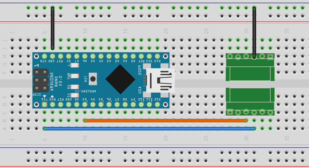
-
-
Results:
-
F24 gives wrong feedback. The Serial Monitor printed:
1 2 3 4FE UC FE UC
-
-
(2024-12-05)
-
Rectify pin connects by separating the 2 groups of serial ports without crossing them.
-
Reasons:
- Figured out the correct usage of SoftwareSerial
-
Actions:
-
Results:
- Garbled characters appears
-
Analysis:
-
The data received by F24 was problematic, and didn’t match its expectations.
I should confirm what data are sent from the Arduino Nano.
-
I can set a breakpoint in the E2 Studio to watch the data that F24 received.
-
-
Blink LED2
Problems:
-
How to download the program to the board?
-
How to use the debugger?
References:
-
Interfacing LED with Renesas RL78 Microcontroller - YouTube - SM training academy
- Played following r1-SM
- Searched by
RL78 blink Ledin DDG
- Searched by
RL78 debug skillin DDG video
Notes:
(2024-11-28)
-
Schematic:
-
When the
P67is set toLow, theLED2will be ON r1-3:38.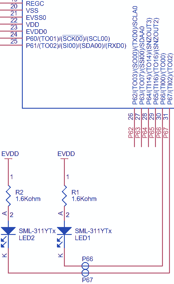
- When the P67 is pulled down, the LED will light.
-
Only need to connect the debugger to the target board. No power supply to the target board.
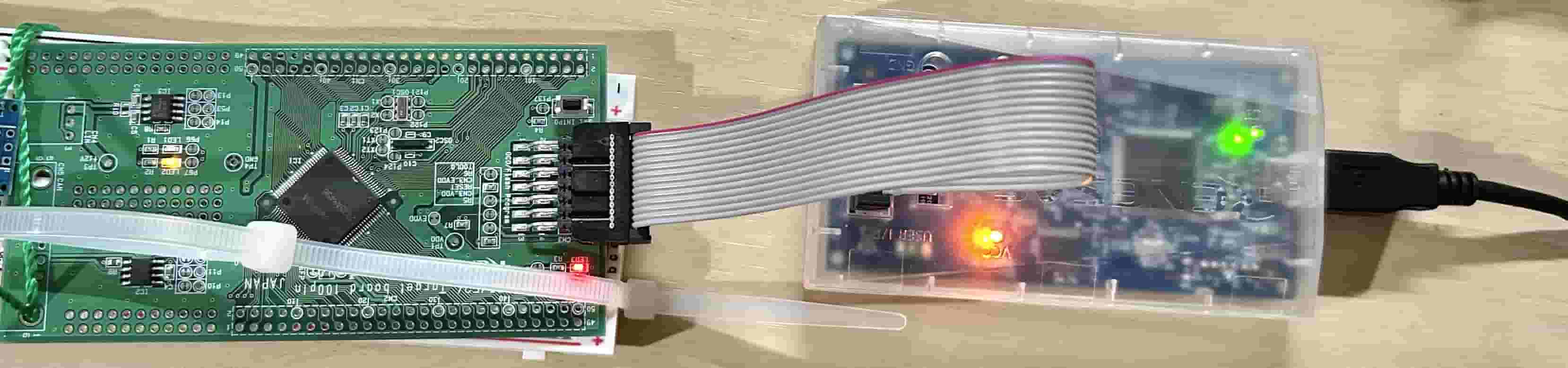
-
-
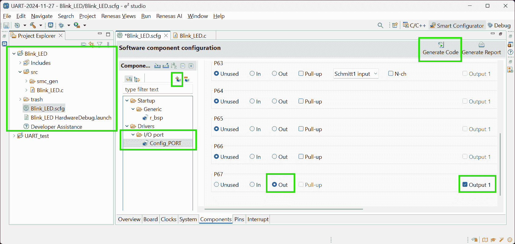
Configure The Components:
-
Blinking
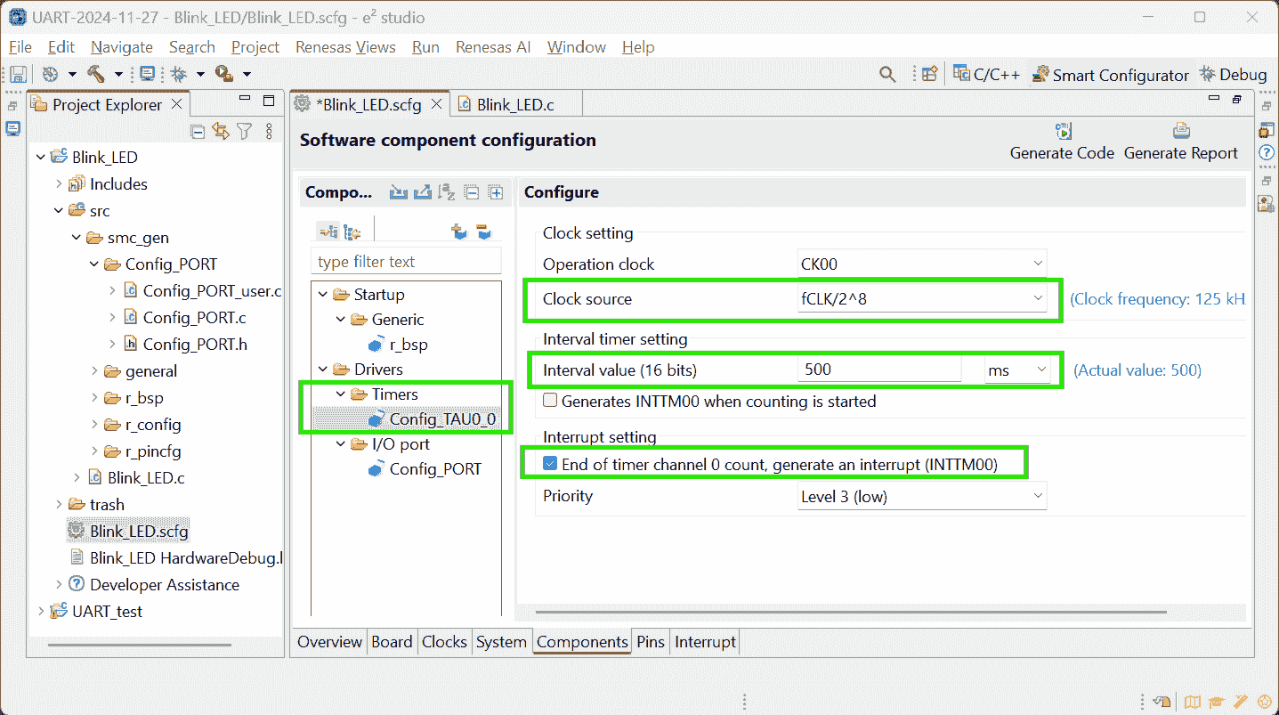
LED2needs to configure 2 components:PortsandTimer Array Unitr3-TutorialComponents Resources Function Setting Ports PORT6 On/Off LED (P67) P67: Output Interval Timer TAU0_0 Toggle LED2 every 500ms Timer: TAU0_0
Counter clock: CK00
Interrupt interval: 500ms
Enable Interrupt (INTTM00)
Interrupt level: Level 3 -
Smart Configurator r1-12:17:
Add component > Ports > Config_PORT > PORT6 > P67
-
If directly check the pin
P67, it’ll NOT be initialized: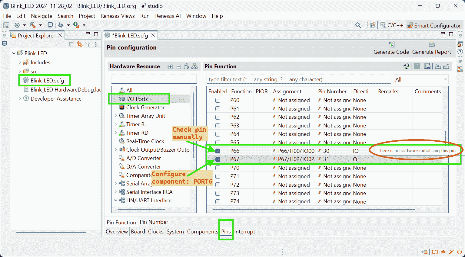
-
-
Smart Configurator: Timer Array Unit
-
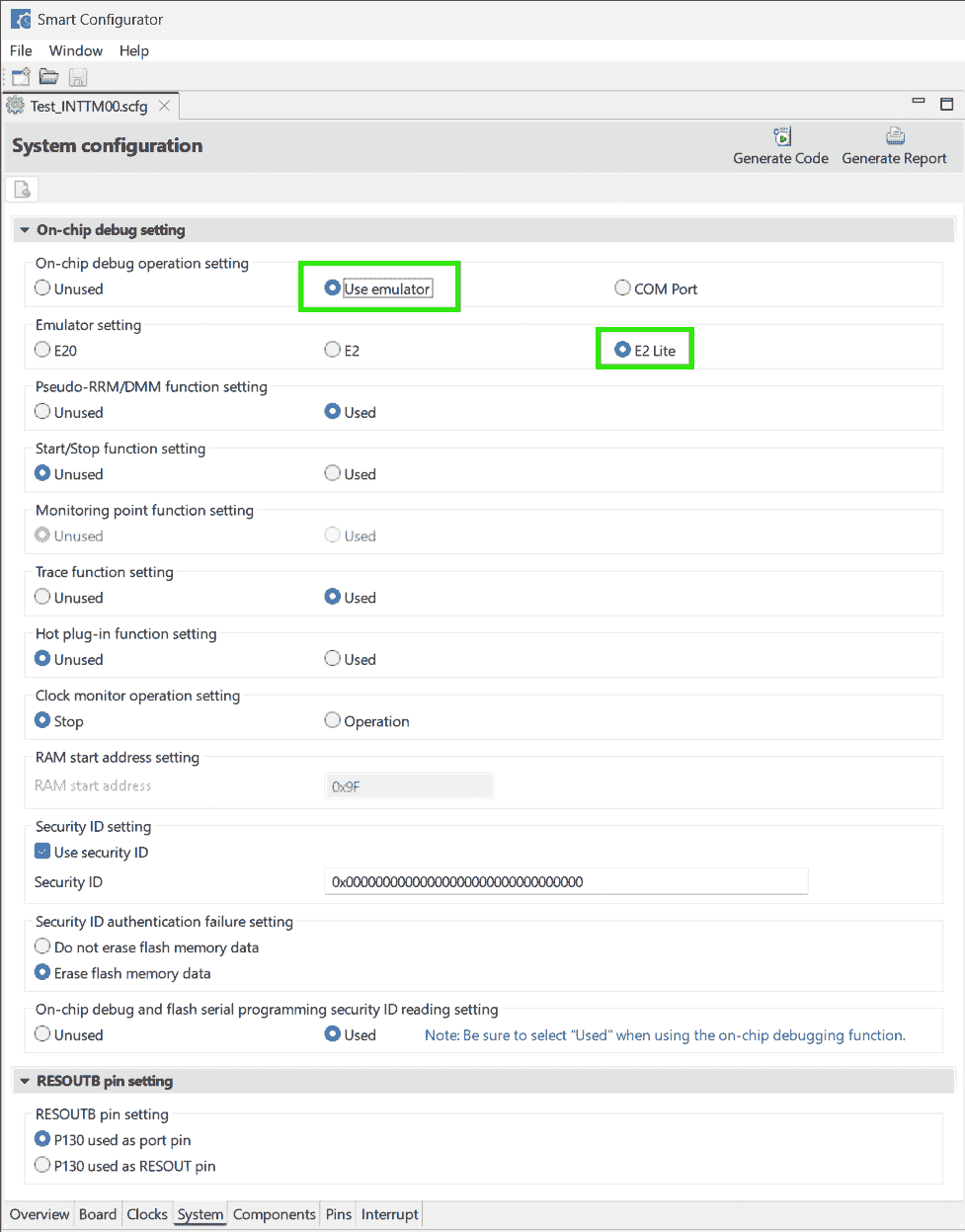
Select using E2 Lite for debugging
-
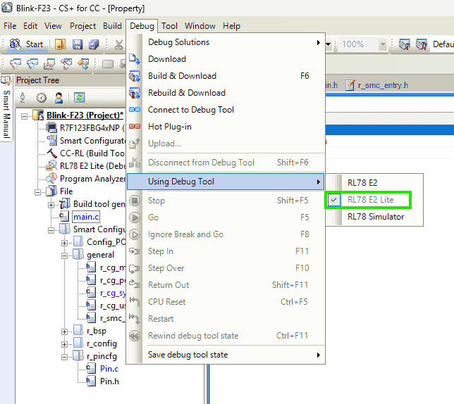
Also, if using CS+, don’t forget to check: Debug > Using Debug Tool
-
-
Click “Generate Code”
-
-
Add User Code and Run Project
-
Config_TAU0_user.c: IncludePin.hand write timer interrupt behavior:1 2 3#include "Pin.h" ... PIN_WRITE(LED2) = ~PIN_READ(LED2);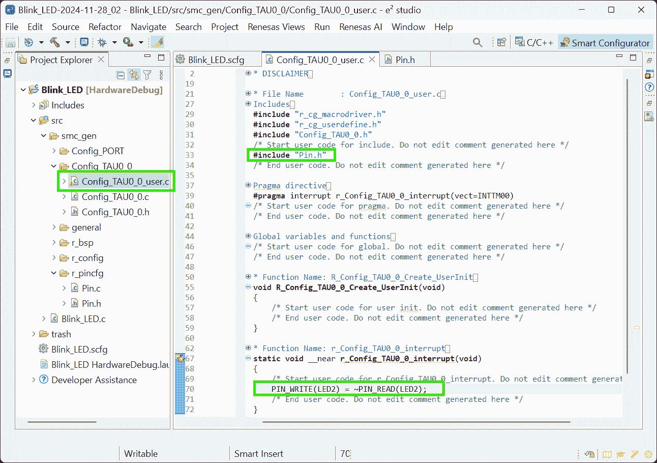
-
Pin.h: Define macro forLED2- Note, the video shows “Users guide”, which doesn’t appear in my
Pin.h
1#define LED2 6,7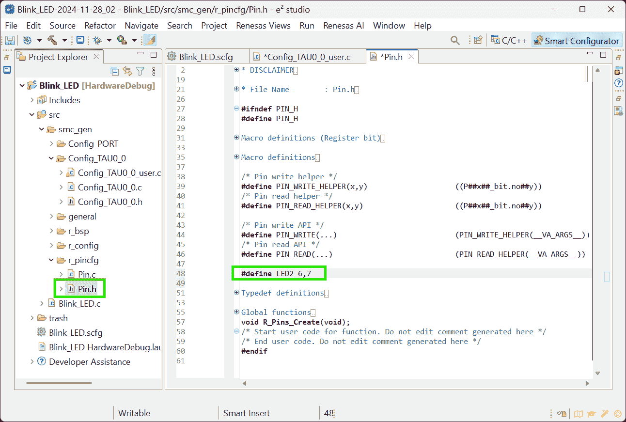
(2024-12-20)
-
Symbolic name can be specified in the Smart Configurator
1 2 3 4 5 6 7 8 9 10 11 12 13 14 15 16 17 18 19 20 21 22// src/smc_gen/r_pincfg/Pin.h /* User's guide for symbolic name. * The generated symbolic names can be used in the user application as follows: * * Example: Toggle LED1 at Pin P54. * There are 2 ways to toggle LED1 * 1) Using symbolic name macro * Assuming the symbolic name for P54 is "LED1", the generated macro definition will be: * #define LED1 5,4 * * To use this macro definition to toggle the LED1, call the symbolic name APIs: * PIN_WRITE(LED1) = ~PIN_READ(LED1) * * 2) Not using symbolic name macro * Call the symbolic name APIs directly * PIN_WRITE(5,4) = ~PIN_READ(5,4) */ /* Symbolic name */ #define MCU_RXD1 1,1 #define MCU_LIN_EN 1,0
- Note, the video shows “Users guide”, which doesn’t appear in my
-
Blink_LED.c:mainfunction.1 2 3 4 5int main(void){ R_Config_TAU0_0_Start(); EI(); while(1); }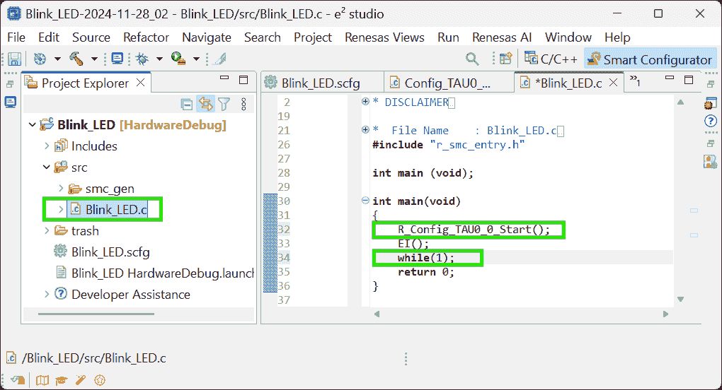
(2025-04-17T15:01:15)
-
If do not use a timer interrupt, the
main()can be:1 2 3 4 5 6 7 8 9 10 11 12 13 14 15 16 17#include "r_smc_entry.h" void delay(long d){ while(d--); } int main(void) { while(1) { PIN_WRITE(LED1) = 0; // ON delay(500000); PIN_WRITE(LED1) = 1; // OFF delay(500000); } return 0; }
-
-
Build project to generate binary file
Project>Build Project
-
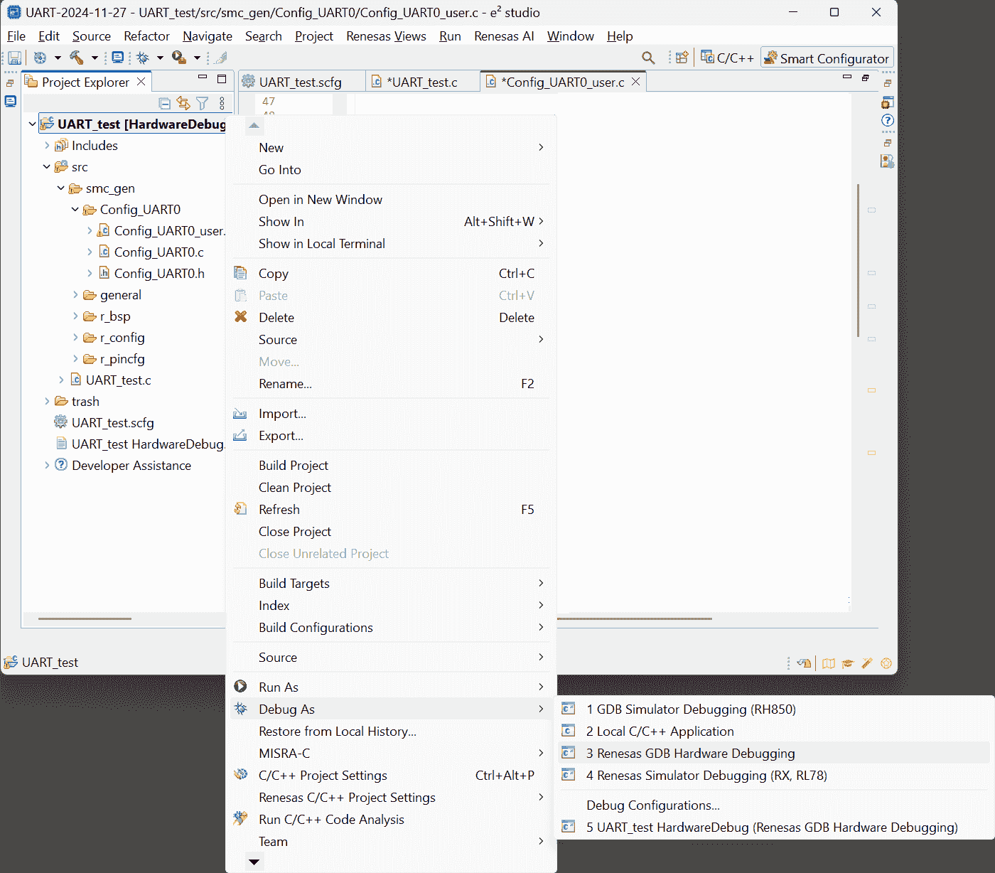
Right-click on the project name > Debug As > 3 Renesas GDB Hardware Debugging
-
Debug configuration (using default settings):
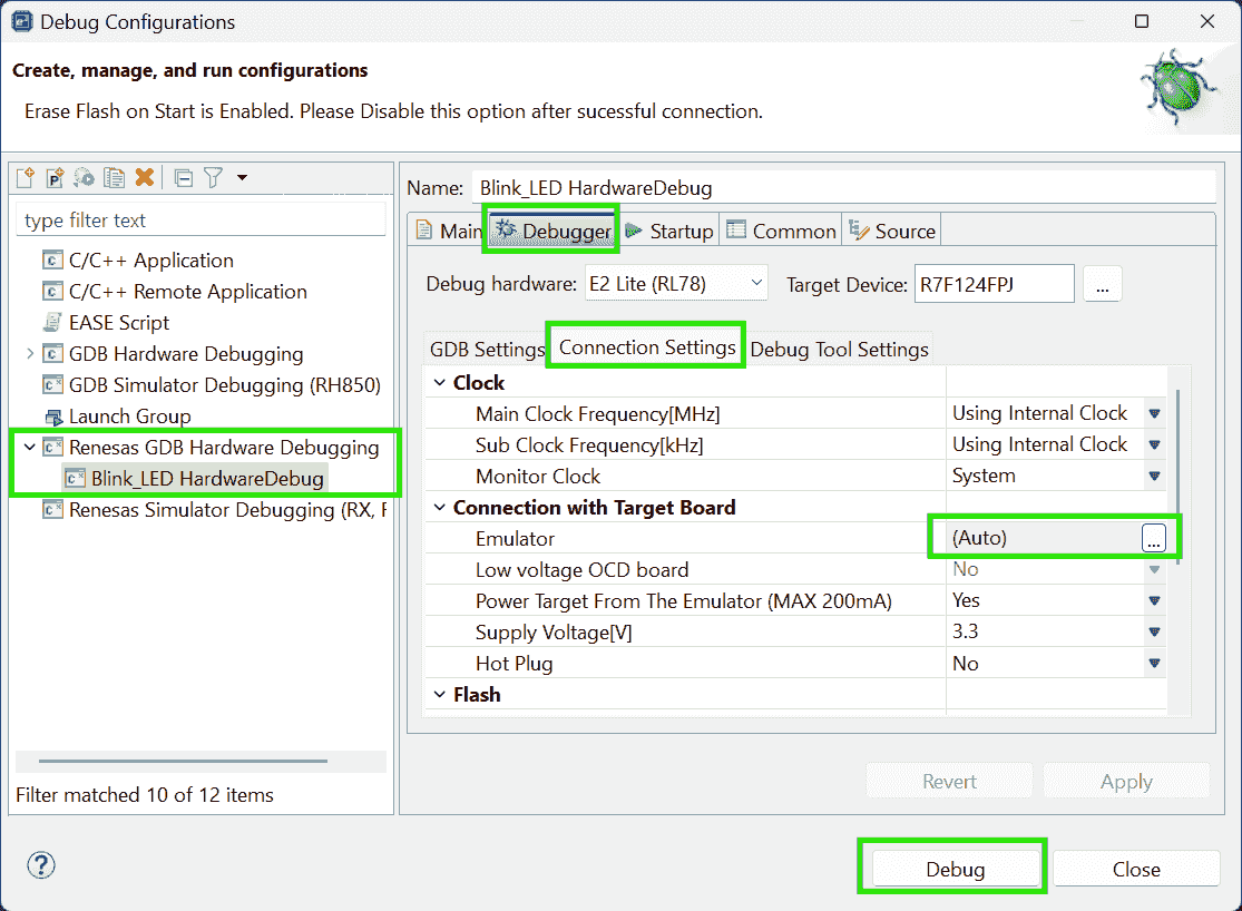
-
Click
Resumebutton to continue the program. The program will stop at the beginning of the main funciton.Click
Resumeagain to start execution.
-
(2024-12-10)
- Add breadpoint by double-cliking and add a global to watch by dragging it to “Expressions” view r4-YouTube.
-
-
SPI
Problems:
(2024-11-29)
- Use RL78/F24 to read values of the pressure sensor Bosch SMP581.
References:
-
ELCL Slave Select Pin Function (4-wire SPI) Tutorial (1/3) - Create project for RL78/G23
- Found on the page: RL78 Smart ConfiguratorSolution Toolkit when looking for solution to burn the hex code to MCU, and entering this page by accidentaly clicking.
- The page is opened when searching (241129)
smart configurator for RL78 F23 UARTin DDG
-
RL78/G23 Handshake-based SPI Master Transmission/Reception Rev.1.01 | Renesas
- Searched by
RL78 SPIin (241206) Renesas search page - Try to search the above keywords after browsing
the search results of
F24 SPI. Total 6 pages don’t include SPI application note.
- Searched by
-
RL78/G10 Serial Array Unit (CSI Master Communication) CC-RL | Renesas
- Searched by s2
-
Sample Code for RL78/G23 Handshake-based SPI Master Transmission/Reception Rev.1.01
- Searched by
R01AN5889JJ0101in Renesas search
- Searched by
-
e² studio Quick Start Guide - Install e² studio and CC-RL Compiler on Linux | Renesas
- Searched by
e2 studio install CC-RLin DDG
- Searched by
-
- Searched by s2
Notes:
-
ELCL (Logic and Event Link Controller)
-
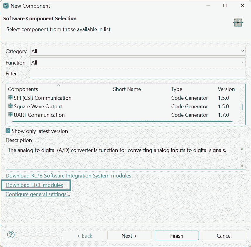
ELCL module can simplify the circuit by reducing 4 wires to 3 r1-Tutorial.
-
The video demonstration uses board: RL78 - G23 64 pin (
R7F100GLGxFB), which has an option of “Download ELCL module”. Although F24 doesn’t have ELCL, it has SPI.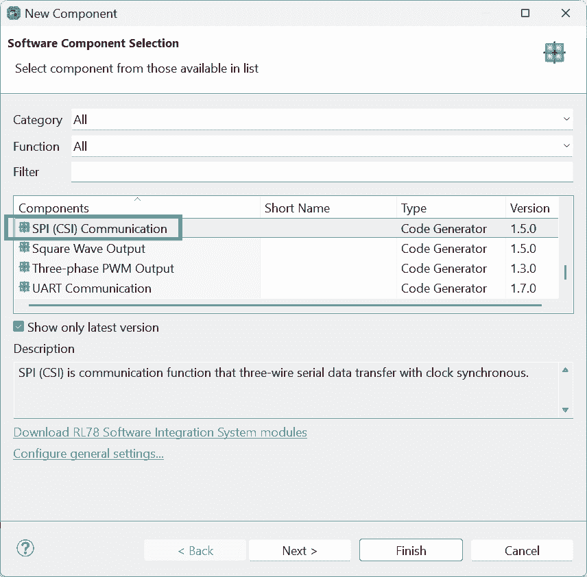
-
ELCL enables an MCU to serve as an slave device, by simulating an “slave selection” signal.
-
(2024-12-06)
-
SPI is a kind of CSI communication r2-G23
-
Transmit/receiveis analogous to theSPI.transfer16()in Arduino: Read 1 byte from the bus and at the same time send 1 byte to the bus.
Sample Code
(2024-12-09)
-
Open the sample project after downloading it r4-Code
-
Actions:
-
Install more packages
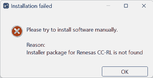
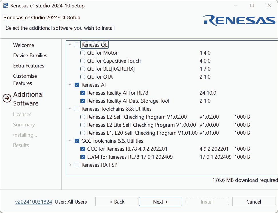
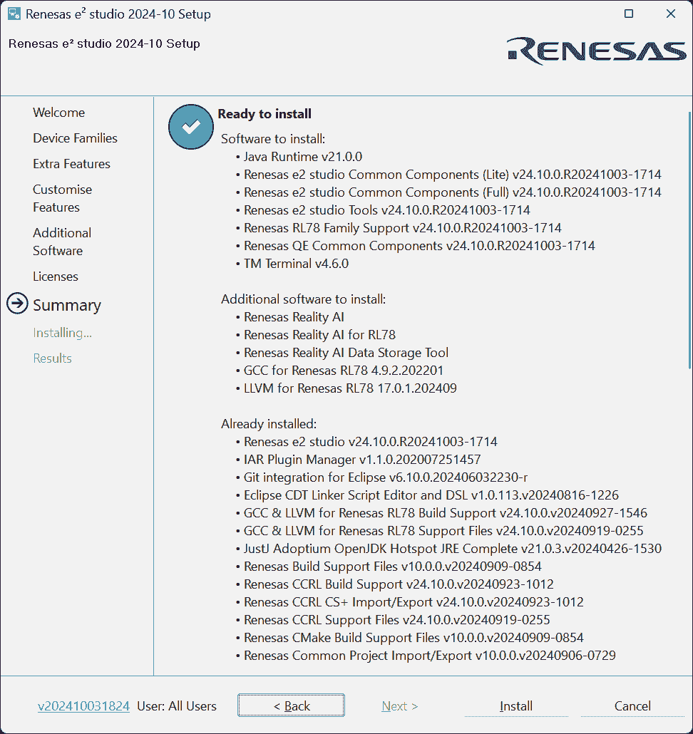
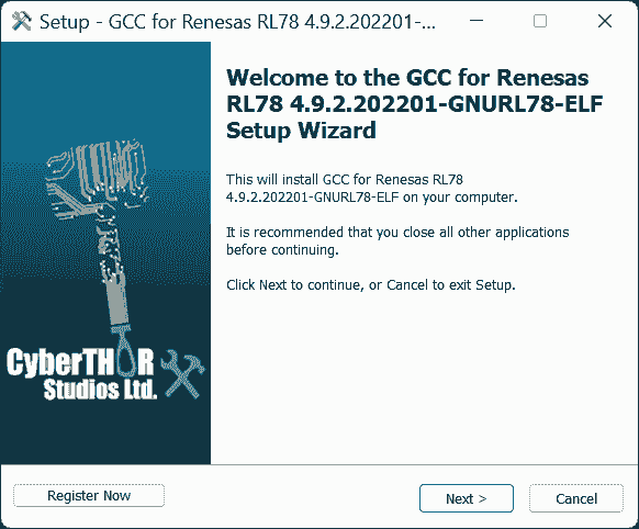
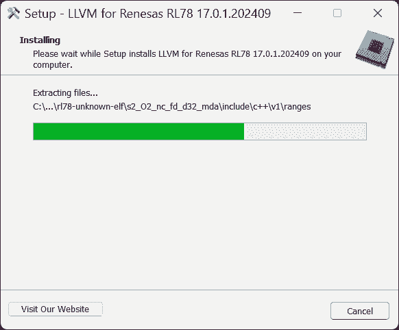
-
installing CC-RL may require license manager r5-Linux
-
-
Results:
-
Those packages are not needed, at least don’t help to open the sample project.
Those packages do not include the required CC-RL compiler.
-
-
-
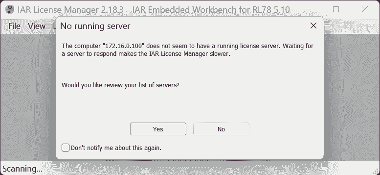
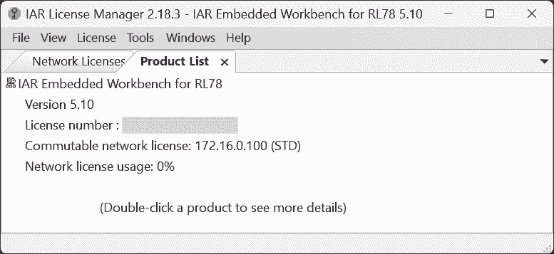
Use IAR, where the company has valid license manager.
-
BTW, CS+ can build the project:
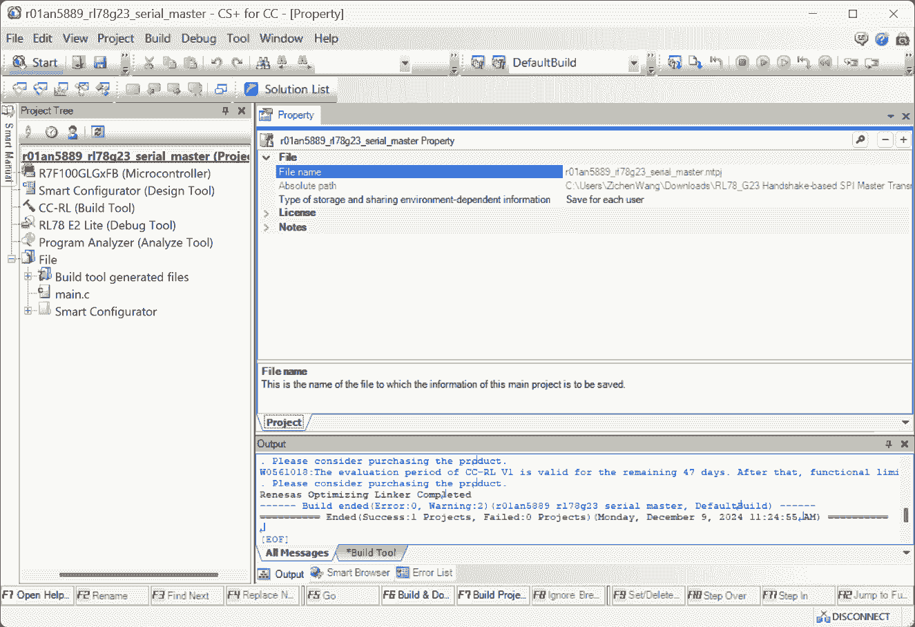
-
-
Config the SPI for F24 based on the sample
.smcgfile-
Reasons:
- The .smcg file in the sample code can be opened with Smart Configuartor.
-
-
The LEDs are used as indicators, the code is not controlling LEDs. See ch 1.5 for objectives description.
-
The
data_lengthis1byte (8 bits). And the arrayuint8_tis containing theuint8_ttype. So, 1 cell stores 1 data.The function:
R_Config_CSI00_Send_Receive()just sends 1 char, and receives 1 char.1 2// Lin #305 R_Config_CSI00_Send_Receive(&g_tx_data, data_length, &g_rx_data); -
The interrupt:
INTCSI00? -
The line #284:
g_num = g_rx_data_stored[0] & 0x3F; -
The
cnt-1in the Line #252:g_rx_data_stored[cnt-1] = g_rx_data -
The
(0x80 > g_rx_data_stored[0])in line #255
SMP581
(2024-12-08)
-
Create Project
-
Configure The Components
-
Actions:
-
Components
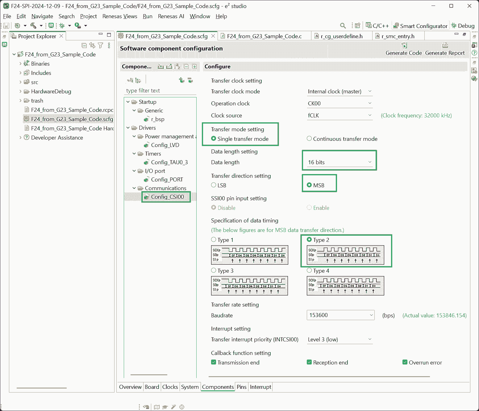
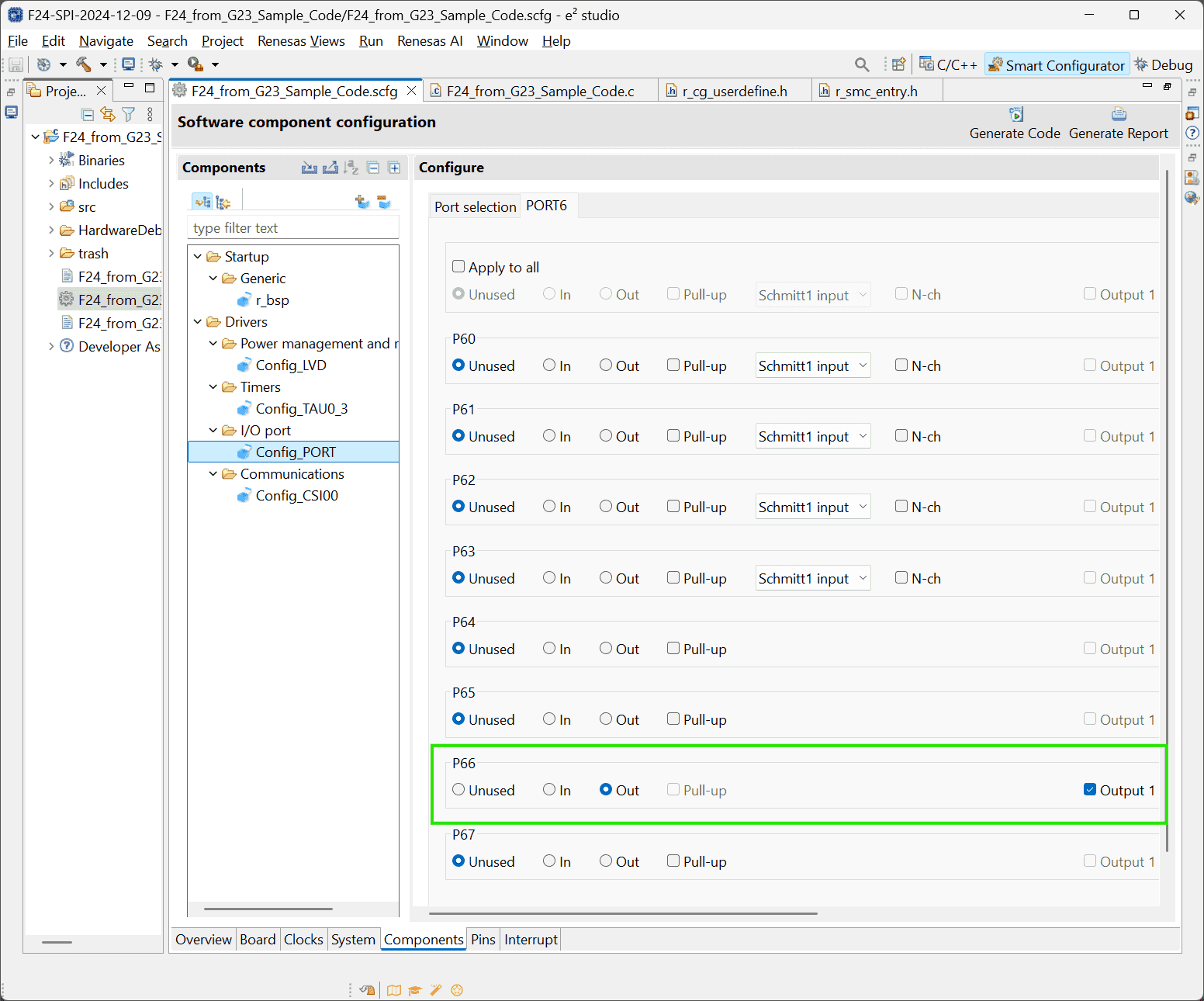
Components Resources Function Setting SPI CSI00 SCK00, SI00, SO00 Ports PORT6 Chip selection P67: Output - If checking the option:
Output 1, the LED is off initially r1-Tutorial.
- If checking the option:
-
Sensor specifics:
-
The sensor is of 16 bits.
-
The
SPI_MODE1of Arduino corresponds to theType 2in RL78
-
-
-
-
Add User Code and Run Project
-
Define the “Chip Selection” pin in
src\smc_gen\general\r_cg_userdefine.h:1#define CS1_pin P6_bit.no6-
In another way, this pin can be called by assigning a symbolic name to it, and then use
PIN_WRITE():1 2 3 4 5// src/smc_gen/r_pincfg/Pin.h #define MCU_Pressure_CS 6,3 // src/hw/hw_smp581.c PIN_WRITE(MCU_Pressure_CS) = 0;
-
-
No response data received:
1 2 3 4 5 6 7 8 9 10 11 12 13 14 15 16 17 18 19 20 21 22uint16_t g_tx_data; /* Send data buffer */ uint16_t g_rx_data; /* Receive data buffer */ const uint16_t data_length = 16; const uint16_t MODE[3] = /* Command code */ { 0B0011000000000000, /* Read pressure, Keep all errors */ 0B0101000000000000, /* Read temperature, Keep all errors */ 0B1001000000000000, /* Config & Identi */ }; void main(void) { R_Config_CSI00_Start(); /* Enable CSI00 module */ CS1_pin =0; /* set CS1 active */ g_tx_data = MODE[0]; while(1U) { R_Config_CSI00_Send_Receive(&g_tx_data, data_length=16, &g_rx_data); } }
-
No Received Data
Problems:
(2024-12-10)
- A few examples r1-Forum indicated that calling SPI is easy. But why I cannot receive data?
References:
-
RL78/G14 SPI - Forum - RL78 MCU - Renesas Engineering Community
- Searched by
RL78 F24 SPI experimentin DDG
- Searched by
-
How to perform SPI interface in Renesas? - Forum - RL78 MCU - Renesas Engineering Community
- Searched by
RL78 F24 SPI experimentin DDG
- Searched by
- RL78/G23 ELCL Slave Select Pin Function (for 4-wire SPI) Application Note Rev.2.00 (R01AN5614EJ0200)
Practices:
(2024-12-10)
-
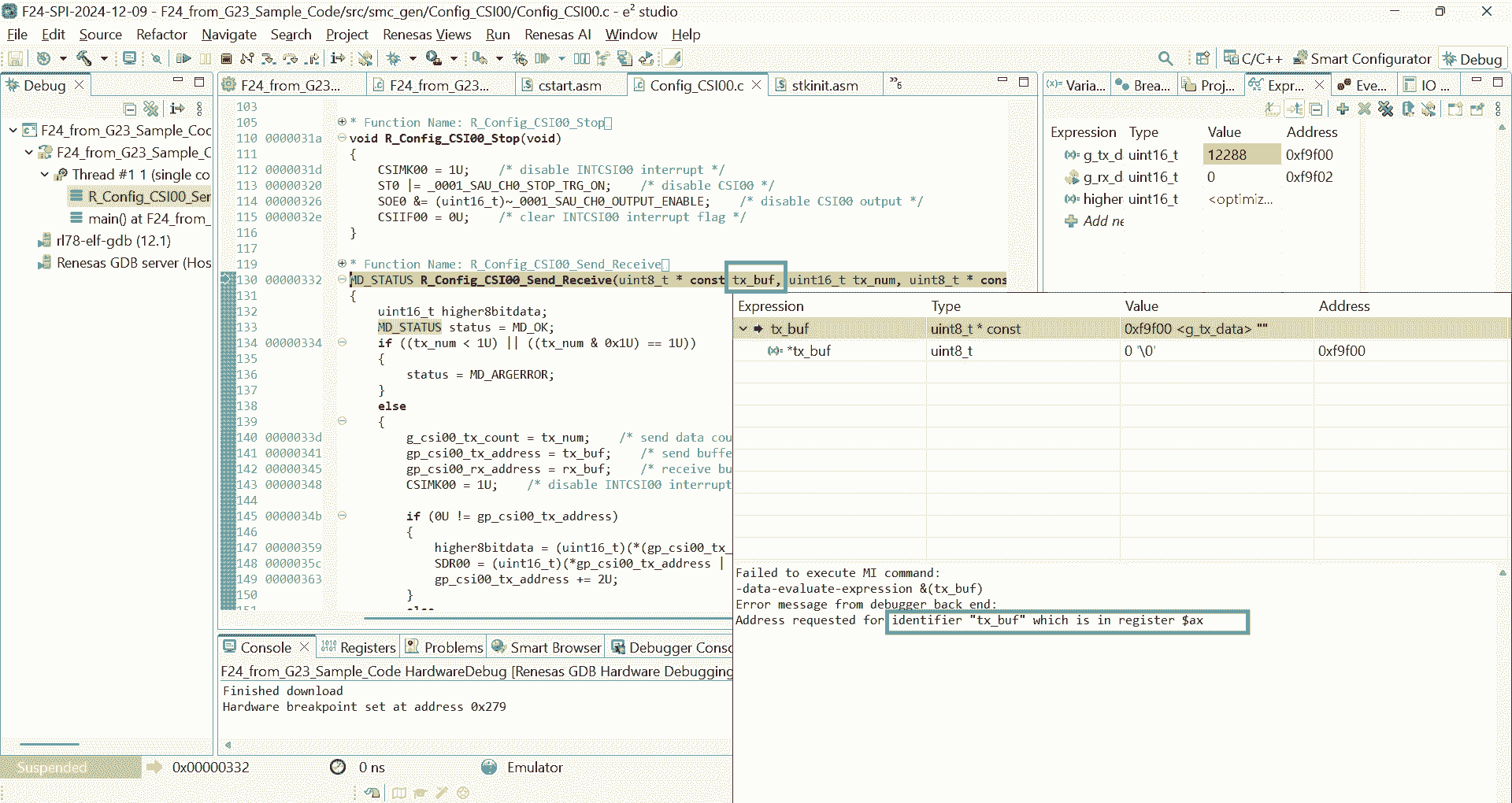
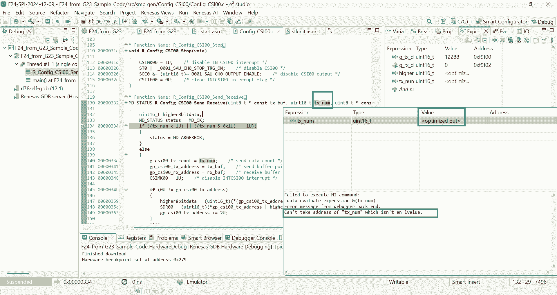
Try to debug.
-
The values passed to the arguments are not displayed
-
(2024-12-12)
-
Take the Arduino code as an example
-
Results:
- The sensor works fine with Arduino
-
Analysis:
-
MISO of the SMP581 should connect to MISO of MCU:
SO00(Serial Output) of RL78/F24.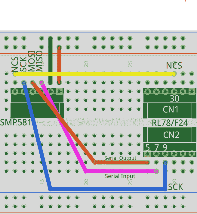
-
Stable power supply is necessary for the sensor to return correct values. Both 5V and 3.3V can make SMP581 work correctly.
Otherwise, unstable voltage (from the sparkfun stick) won’t enable the SMP581 return data, only 0.
-
-
-
Use RL78/F24 to provide the CS signal.
-
Actions:
- Keep the
CS1_pinalways low and connect it to SMP581.
- Keep the
-
Results:
-
Constant low voltage doesn’t let the sensor return data.
If there is only
digitalWrite(ssPin, LOW);withoutdigitalWrite(ssPin, HIGH);, no returned data:1 2 3 4 5 6 7 8 9 10 11 12Requesting Temperature Value and Diagnosis... Cmd has been transfered Data received: 101000000000000 Diag bits rmvd: 0 Number of LSB: 0 Current temperature (℃): 10530.32 Requesting Pressure Value and Diagnosis... Cmd has been transfered Data received: 101000000000000 Diag bits rmvd: 0 Number of LSB: 0 Current pressure (kPa): 60.00
-
-
Analysis:
- Delay is necessary for SMP581 to return, which is also mentioned in r2-Forum
-
-
Use a LED-blinking
INTTM00of RL78/F24 to control the CS, and the MISO and MOSI are connected to Arduino-
Results:
- Data received by Arduino is not correct.
-
Analysis:
- The CS pin turning on and off should be together with the data transfer function.
-
-
✅ Use syntex turning the
CS1_pinON and OFF to surround the data transfer function:-
Reasons:
- To mimic the Arduino code.
- Shown in the forum post r2-Forum
-
Actions:
1 2 3 4 5 6 7 8 9 10 11 12 13 14 15 16 17 18void delay(long d){ while(d--); } int main(void) { EI(); R_Config_CSI00_Start(); /* Enable CSI00 module */ while(1U) { CS1_pin = 0; /* Select the sensor by pulling the pin down */ g_tx_data = MODE[0]; result = R_Config_CSI00_Send_Receive(&g_tx_data, data_length, &g_rx_data); delay(1000000); CS1_pin = 1; } return 0; } -
Results:
-
The
g_rx_datacan keep changing (21274or21270):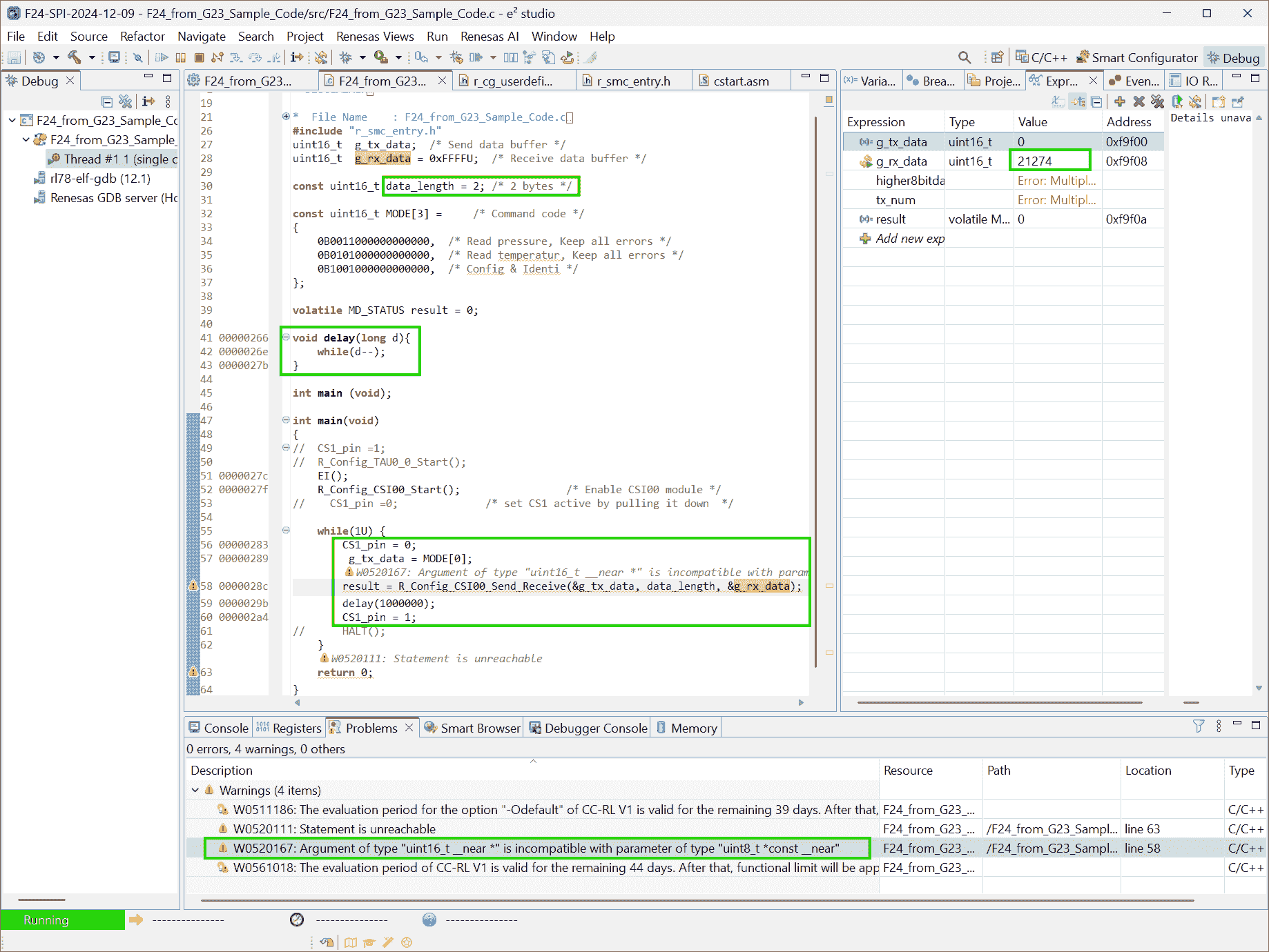
-
The converted physics values: Pressure (㎪) and temperature (℃) are similar to Arduino results.
commit: 7ba9e25 (
C:\Users\ZichenWang\e2_studio\workspace\F24-SPI-2024-12-09\F24_from_G23_Sample_Code)
-
-
Analysis:
-
Do Not Use Delay
Problems:
-
The
mainfunction is a loop. Thedelay()will make the main loop wait there, and cannot perform other services.Therefore, a “waiting state” can be set in the state machine for a function.
Notes:
(2024-12-23)
-
The function is divided into 3 states by the “delay” state:
-
The original function:
1 2 3 4 5 6 7void bsp_spi_read_adc_smp581(uint16_t* tx_data_addr, uint8_t data_length, uint16_t* rx_data_addr) { CS1_pin = 0; /* Chip selection */ R_Config_CSI00_Send_Receive(tx_data_addr, data_length, rx_data_addr); /* The returned SPI data will be stored in rx_data*/ delay(1000000); CS1_pin = 1; /* Chip deselection*/ } -
Convert the function to a state machine:
1 2 3 4 5 6 7 8 9 10 11 12 13 14 15 16 17 18 19 20 21 22 23 24 25 26 27static uint8_t state = 0; static uint32_t start_time; void bsp_spi_read_adc_smp581(uint16_t* tx_data_addr, uint8_t data_length, uint16_t* rx_data_addr) { switch (state) { case 0: CS1_pin = 0; /* Chip selection */ R_Config_CSI00_Send_Receive(tx_data_addr, data_length, rx_data_addr); current_time = service_get_1_ms(); state++; break; case 1: if ((service_get_1_ms()-start_time)>1000) { state++; } break; case 2: CS1_pin = 1; /* Chip deselection*/ state = 0; break; } }
-
Single Cmd Caused NC
(2024/01/04)
Problems:
-
When dubugging the project: F24-SPI-2024-12-09 (
8034804d), the value keeps 100.xx unchanged. -
The sensor works fine when connected to Arduino Nano
-
The previous version before converting to layer-wise code seems to work fine.
-
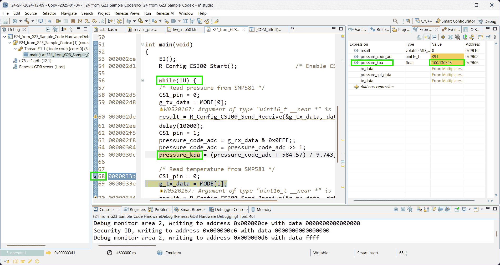
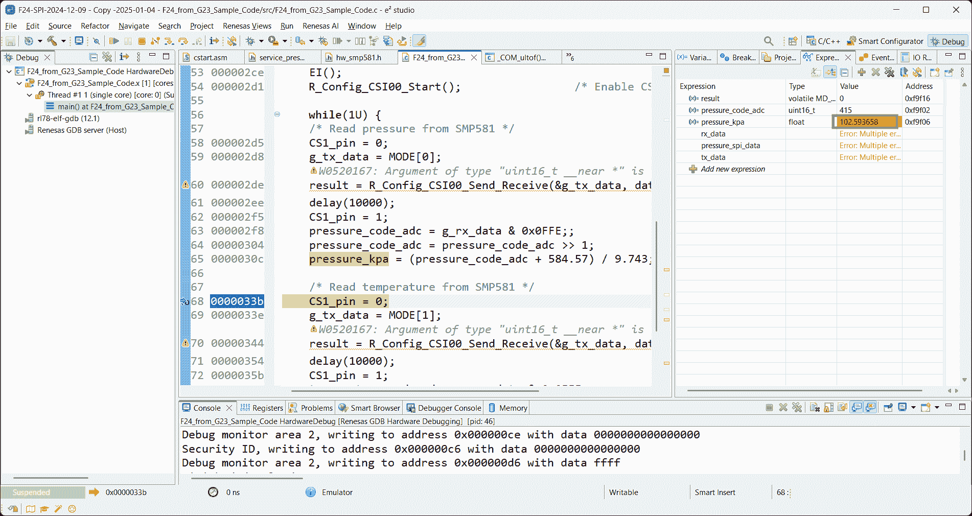
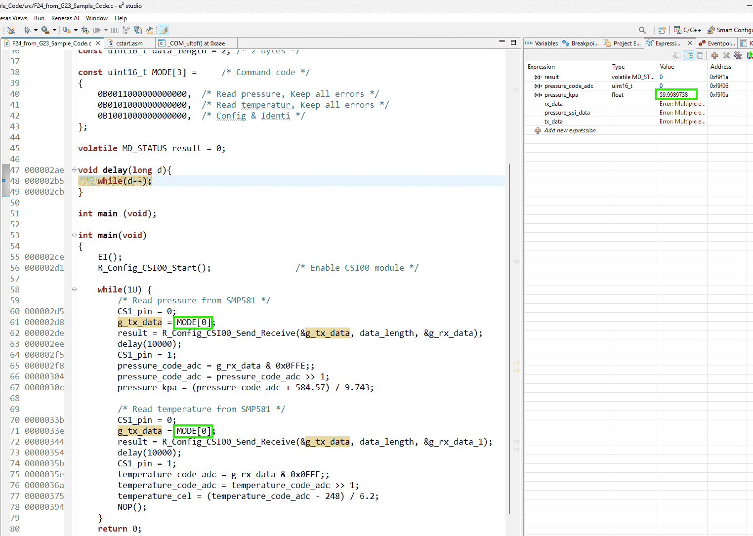
Image-1 shows the first pause at the breakpoint after
pressure_kpahas been converted. -
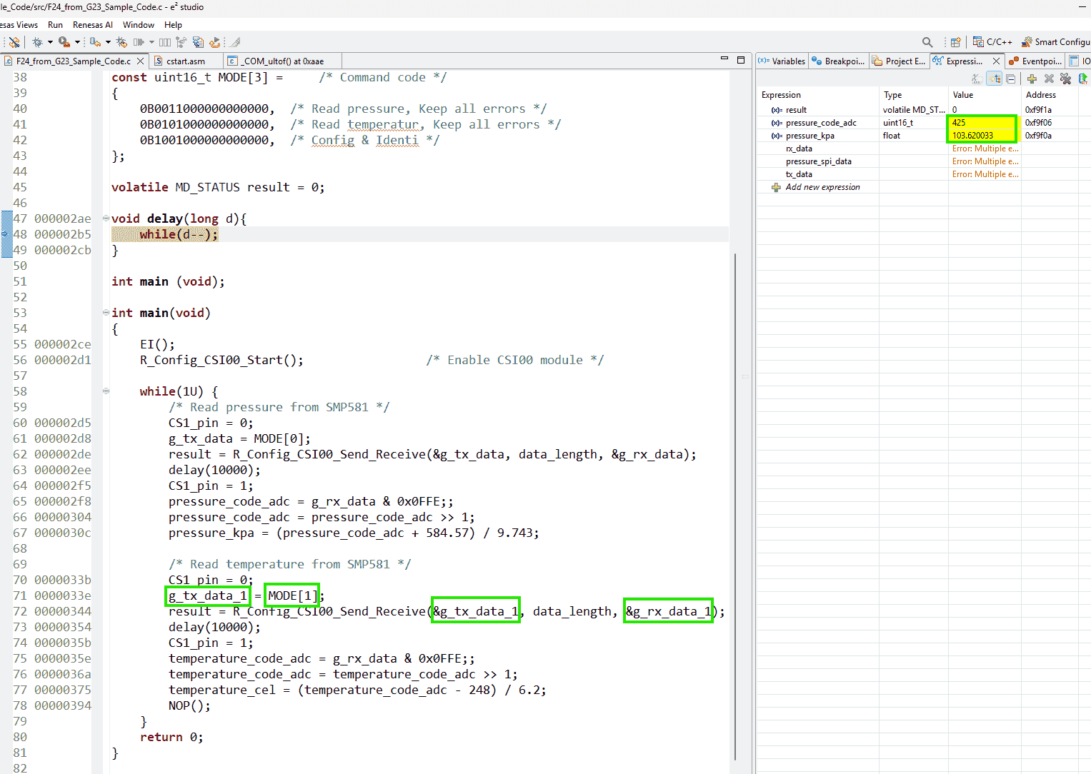
Image-2 shows the second pause. The pressure can be updated promptly without getting stuck.
-
(2025-01-08)
- A single
mainfunction for F24 can get the updating pressure values, but the layer-wise code get the pressure value unchanged: 100.130348 (21262).
(2025-01-09)
-
Keep sending the pressure-request command only will cause the sensor not response. The
pressure_kparemains59.9989unchanged, which is the same as the value that the Arduino code printed, without connecting to the sensor.-
I found this problem because I initially want to change the “workable version” little by little utill get to the “layer-wise code” version.
By doing this, I believe I can what step is problematic. The first step I tried is removing the temperature reading part. After doing that, the code appears the same problem: stucks at
59.9989. -
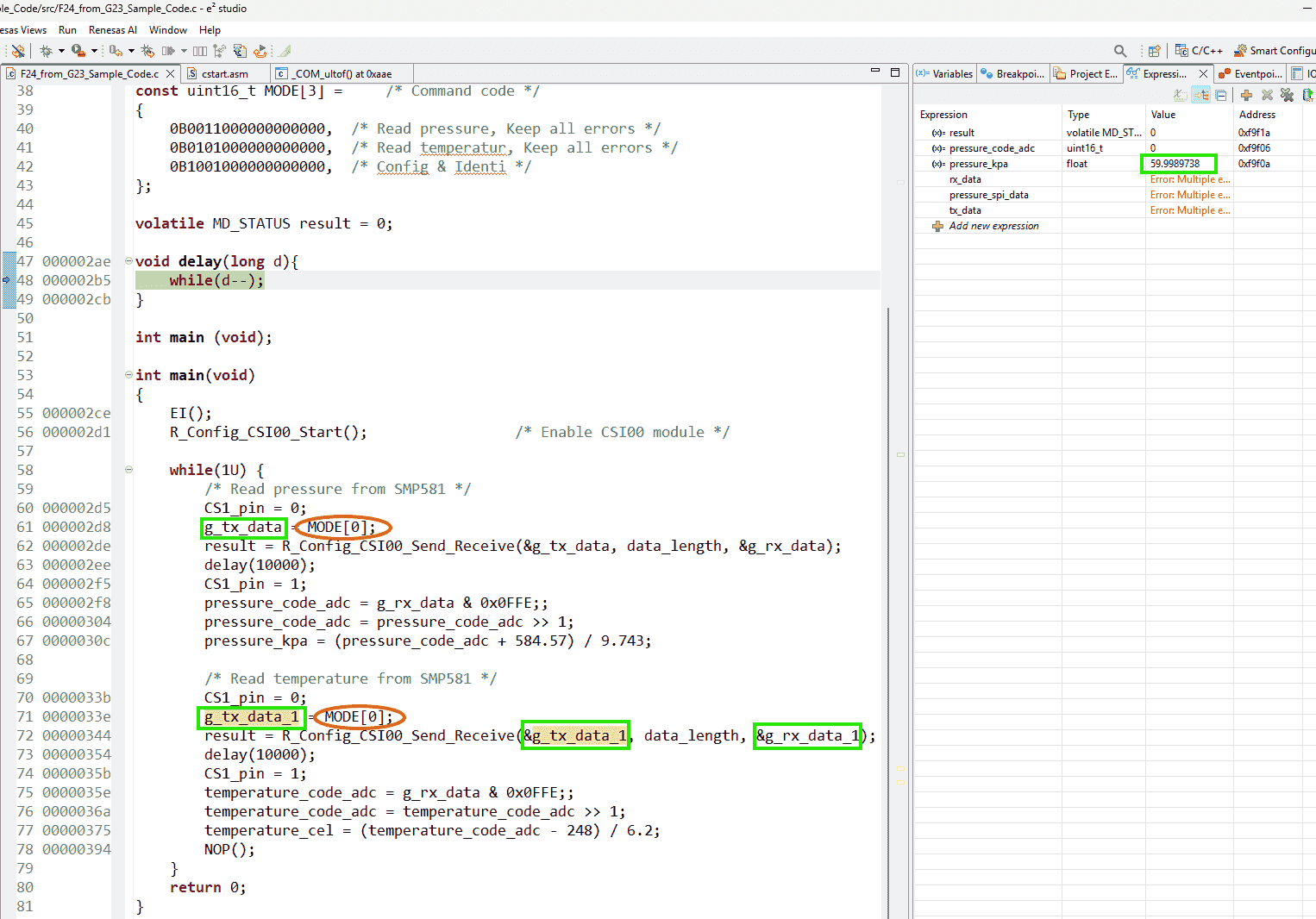
Sending the pressure-requesting command twice doesn’t work either.
-
Even using different variables doesn’t fix it.
-
References:
Addressing:
1. Use UART to print values, rather watching values during debugging
(2024-01-09)
- Sending pressure-requesting and temperature-requesting commands together
Value Keep Increasing
Problems:
- The pressure value read from sensor only increases and never drops, so the value after the first reading are not correct.
Issues:
Addressing:
-
Reproduce error by porting previous project of F24 - FPJ3A (“F24-SPI-2024-12-09”) testing the Shuttleboard.
-
Actions:
-
Smart configurator only set 2 modules: SPI and Port (1 pin: P63)
Then copy the main function.
Add a breakpoint at the first sentence in the while loop:
P6_bit.no3 = 0;1 2 3 4 5 6 7 8 9 10 11 12 13 14 15 16 17 18 19 20 21 22 23 24 25 26 27 28 29 30 31 32 33 34 35 36 37 38 39 40 41 42 43 44 45 46 47 48 49 50 51 52 53 54 55#include "r_smc_entry.h" uint16_t g_tx_data; /* Send data buffer */ uint16_t g_rx_data = 0xFFFFU; /* Receive data buffer */ uint16_t pressure_code_adc; uint16_t temperature_code_adc; float pressure_kpa; float temperature_cel; const uint16_t data_length = 2; /* 2 bytes */ const uint16_t MODE[3] = /* Command code */ { 0B0011000000000000, /* Read pressure, Keep all errors */ 0B0101000000000000, /* Read temperatur, Keep all errors */ 0B1001000000000000, /* Config & Identi */ }; volatile MD_STATUS result = 0; void delay(long d){ while(d--); } int main (void); int main(void) { EI(); R_Config_CSI00_Start(); /* Enable CSI00 module */ while(1U) { /* Read pressure from SMP581 */ P6_bit.no3 = 0; g_tx_data = MODE[0]; result = R_Config_CSI00_Send_Receive(&g_tx_data, data_length, &g_rx_data); delay(1000000); P6_bit.no3 = 1; pressure_code_adc = g_rx_data & 0x0FFE;; pressure_code_adc = pressure_code_adc >> 1; pressure_kpa = (pressure_code_adc + 584.57) / 9.743; /* Read temperature from SMP581 */ P6_bit.no3 = 0; g_tx_data = MODE[1]; result = R_Config_CSI00_Send_Receive(&g_tx_data, data_length, &g_rx_data); delay(1000000); P6_bit.no3 = 1; temperature_code_adc = g_rx_data & 0x0FFE;; temperature_code_adc = temperature_code_adc >> 1; temperature_cel = (temperature_code_adc - 248) / 6.2; NOP(); } return 0; }
-
-
Results:
-
Although the pressure returned from the inidividual sensor on the Shuttleboard may be not accurate, the value maintains around 102 kPa. However, the values of sensor on E41 board grows gradually.
It maybe only record the history highest value.
-
Even redownloding the code to MCU, the variable shown in the Watch windows keeps last value! (Redownloading is because I accidentally pressed F6 beside F5.)
-
I also tested: Resetting the value of
g_rx_datato 0 after each reading. But theg_rx_dataalways still keeps grow, instead of oscillating around the normal atm pressure.
-
-
Analysis:
-
I guess this could be hardware problem. The register inside the sensor could never be reset after each reading.
I think this is not a software issue, as the same code works correctly with the individual SMP581 sensor. I suspect the reason may be that some buffer inside the sensor may not be reset after each reading, because during my debugging, when I redownload the program, the sensor returns the value from the previous debugging session.
-
-
(2025-02-11)
-
Correct Timing
-
Reasons:
- The technical support suspected the timing is problematic.
-
Actions:
-
Determine the timing through oscilloscope.
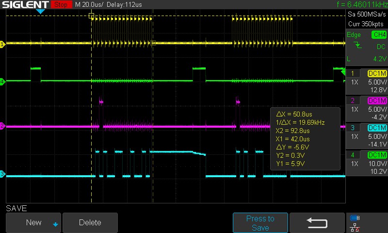
-
Adjust the timing
1 2 3 4 5 6PIN_WRITE(CS_PIN) = 0; delay(50); g_tx_data = MODE[0]; result = R_Config_CSI00_Send_Receive(&g_tx_data, data_length, &g_rx_data); delay(200); PIN_WRITE(CS_PIN) = 1;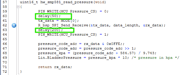
- I think using interrupt is a better way.
-
-
(2025-02-12)
-
Test the SPI interrupt function
1 2 3 4 5 6 7 8 9 10 11 12 13 14 15 16 17 18 19 20 21 22 23 24 25 26 27 28 29 30 31 32 33 34 35 36 37 38 39 40 41 42 43 44 45 46 47 48 49 50 51 52 53 54 55 56// main.c uint8_t g_tx_data[2]; /* Send data buffer */ uint8_t g_rx_data[2] = 0xFFU; /* Receive data buffer */ uint16_t pressure_code_adc; float pressure_kpa; const uint16_t data_length = 2; const uint8_t TX_DATA[] = /* Command code */ { 0B00110000, 0B00000000, /* Read pressure, Keep all errors */ 0B01010000, 0B00000000, /* Read temperatur, Keep all errors */ 0B10010000, 0B00000000, /* Config & Identi */ }; volatile MD_STATUS result = 0; void delay(long d){ while(d--); } int main(void) { R_Config_TAU0_3_Higher8bits_Start(); /* 1ms interval timer start */ R_Config_CSI00_Start(); /* Enable CSI00 module */ while(1U) { /* Wait for 1 ms */ DI(); while (TMIF03H == 0U) { HALT(); } TMIF03H = 0U; /* Issue Chip Select Signal */ P6_bit.no3 = 0; /* Read pressure from SMP581 */ EI(); // Enable lower interval 16 us? result = R_Config_CSI00_Send_Receive(&TX_DATA, data_length, &g_rx_data); HALT(); delay(200); // I found this delay is necessary P6_bit.no3 = 1; pressure_code_adc = ((g_rx_data[0] & 0x07) << 7) | ((g_rx_data[1] >> 1) & 0x7F); pressure_kpa = (pressure_code_adc + 584.57) / 9.743; NOP(); } return 0; }
Parse Diagnostic Bits
Problems:
- Implement the diagnostic function for the pressure sensor SMP581
Addressing:
(2025/03/31)
-
Ask DeepSeek to generate code based on provided information
-
Reasons:
- I don’t use windsurf as I need to remove the words: SMP581 from the source code. The datasheet of SMP581 is not public.
-
Actions:
-
Feed the related information in documentation along with the current
service6.3.2.2 Definition of the Bit Stream Coming from the sensor
Slave Response Variant1 16 bits: Diagnostic bits (bit 15 – 11): These 5 bits transmit the diagnostic information of the sensor and reflect possible failures of the sensor. Data bits (bit 10 – 1): These 10 data bits contain the value (pressure / temperature) requested by the master. Parity (bit 0): The slave response is safeguarded by an odd parity over bits 15 to 1. Even (including 0) will lead to a 1, odd will lead to a 0.
6.3.2.3 Diagnostic Bits
In 16 bit SPI mode, the sensor transmits diagnostic information via diagnosis bits Diag0…4 (bits 11…15) when answering master requests for pressure/diagnosis or temperature/diagnosis. The sensor recognizes errors and transmits diagnostic codes given in the table below. In case of multiple errors, the sensor sends the failure with the highest priority. In case of an error, the sensor continues to send pressure and temperature values.
Diagnosis code
Failure Detection Priority (1= highest) D15 D14 D13 D12 D11 Sensor memory error OTP: At start up, RAM: Continuous 1 1 0 0 0 0 Acquisition chain failure At start up 2 0 1 0 0 0 Pressure sensing element failure* At start up/ Continuous 3 0 0 1 0 0 ADC’s upper limit Continuous 4 0 0 0 1 0 ADC’s lower limit Continuous 5 0 0 0 0 1 No error Continuous 6 0 1 0 1 0 - Pressure sensing element failure - bond failure of pressure signal monitored only at Startup. Bond failure of sensing element supply and temperature-diode monitored continuously.
In addition to the diagnosis codes above, the sensor recognizes communication errors. Communication errors are: • The usage of an invalid command
• Communication cycles with the number of clock cycles during NCS low (active) being not equal to a multiple (including 0) of 16.
The sensor then responds with “0b0000 0000 0000 0001” in the next communication cycle.
-
-
LIN Blink LED
Problems:
-
I need to implement LIN communication. Usually, in a LIN network, there is a single Master and multiple slaves.
However, I currently have only one RL78/F24 board. Also, I don’t have Babylin or other emulators to simulate the host computer.
So, I plan to test the communication between PC and the target board via the UART and LIN protocol base on documents r2-SIS.
-
If it’s possible to let the F24 be a master r1-Master, sending frames, which ask the UART to transmit something?
-
F24 has 2 LIN channels! which be separately set as a master and a slave.
But how to write code for different channels on a single MCU?
-
-
How to call RLIN api?
(2024-12-03)
- Simple project: Master channel send a commend to the slave channel to perform the behavior: blinking the LED.
Create E2 Studio Project
References:
-
RL78/F13, F14 Group LIN Slave Mode (RLIN3) Rev.1.02
- Shared by Joseph
- I think he found it by searching
F13 RLINin Renesas Search page
-
RL78/F2x RLIN3 Module Software Integration System Rev.1.00
- Searched by
F23 RLINin Renesas Searche page
- Searched by
- How to Create a LIN Project with Smart Configurator on e² studio - YouTube - RenesasPresents
- Chapter 5 - How to Build LIN Application | RLIN3 Module Software Integration System
Smart Configurator
Notes:
(2024-12-04)
-
Create an e2 studio project r3-YouTube:
-
Actions:
-
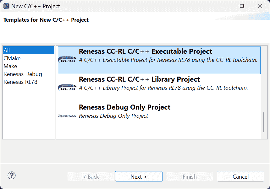
File > New > Renesas C/C++ Project > Renesas RL78
-
“Renesas CC-RL C/C++ Executable Project”
-
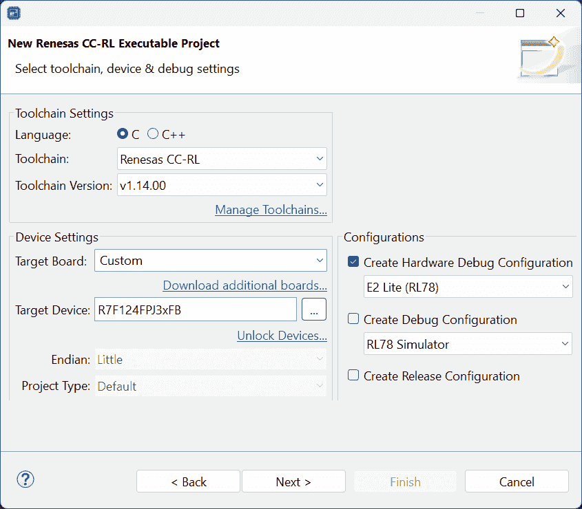
Project Name: F24_Two_LIN_Channels_Blinking_LED
-
Target board: RL78 - F24 100pin > R7F124FPJ3xFB;
Create Hardware Debug Configuration: E2 Lite (RL78)
-
-
Use Smart Configurator
-
Clocks >
Base frequency: 40 MHz >High-speed on-chip oscillator: 40 MHz > CheckLIN0 clockandLIN1 clock -
Components >
r_bsp> Enable: StartClock, Set~, Change~, -
Add Components > rlin3
-
r_riln3>RLIN3 channel0 setting>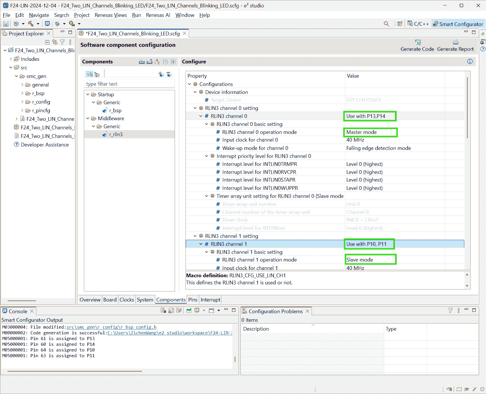
-
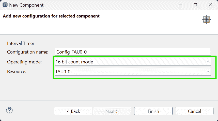
Add Components > Interval Timer > 16 bit count mode (Resource: TAU0_1) >
Operation clock: CK00; Clock source: fCLK/2^8; Interval value: 30 ms
- The master requires schedule implemented based on a timer r2-RLIN3 p39.
-
Add Components > Ports > PORT6
P66 > Out > Output 1
-
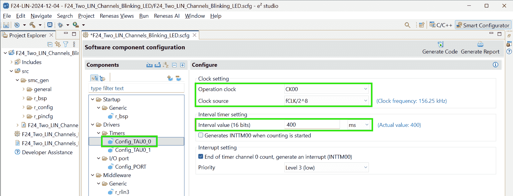
Add Components > Interval Timer > 16 bit count mode > TAU0_0
Operation clock: CK00; Clock source: fCLK/2^8; Interval value: 400ms Interrupt setting check: End of timer channel 0 count, generate an interrupt (INTTM00)
-
A change pops when generating code:
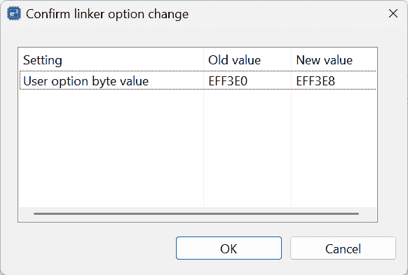
-
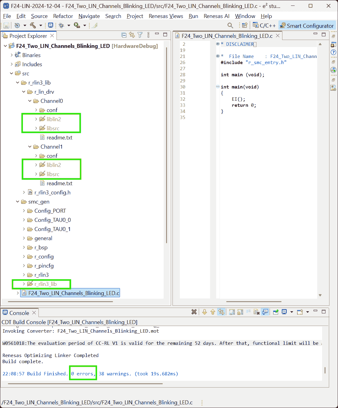
Copy the Smcg generated lib:
r_rlin3_libto under thesrc/.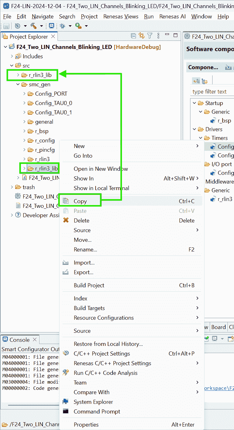
-
-
-
LIN Configurator
-
Actions:
-
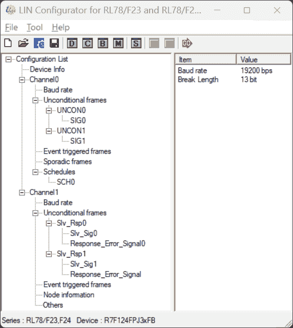
Use LIN Configurator for RL78/F23_F24 to setup LDF:
-
Set Baud rate for both channels to 19200
-
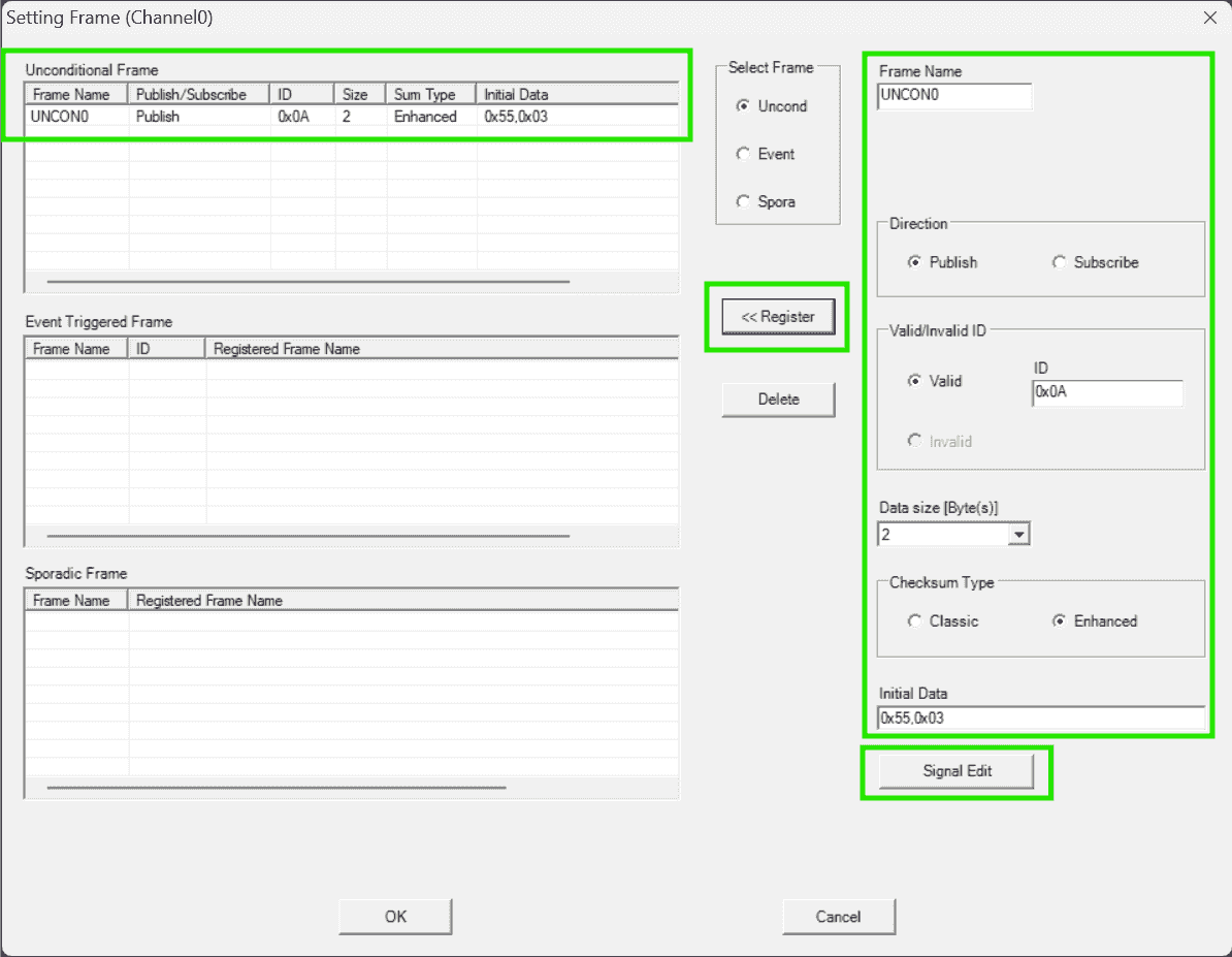
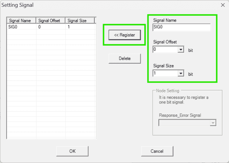
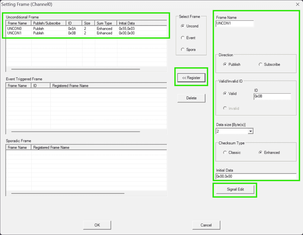
Set an unconditional frame for the Master: channel0
-
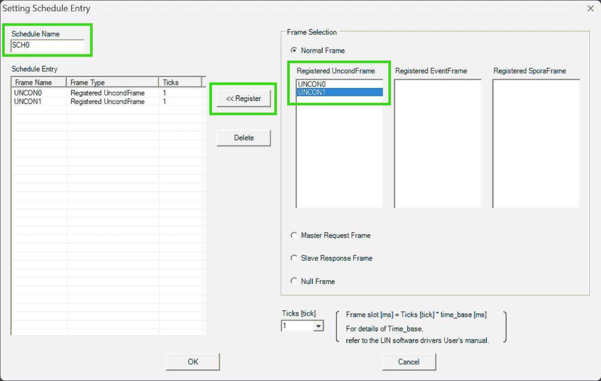
Set schedule for the Master channel: Transmit these two frames repeatedly
-
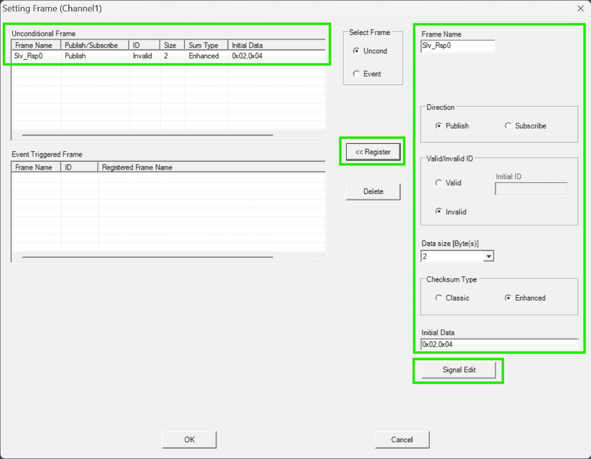
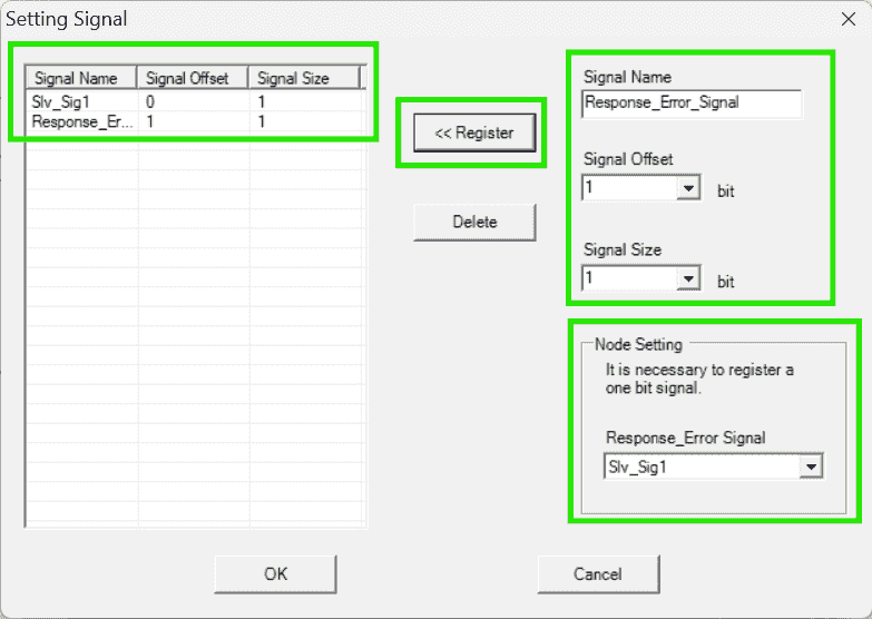
Set frames for Slave: Channel1, Publishing responses
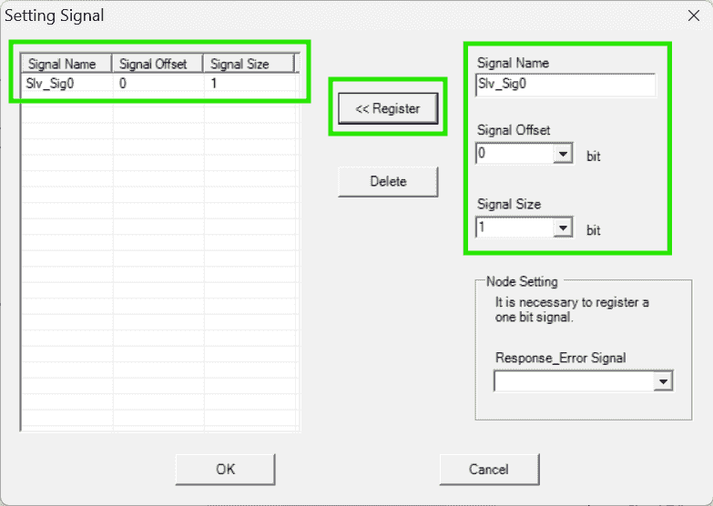
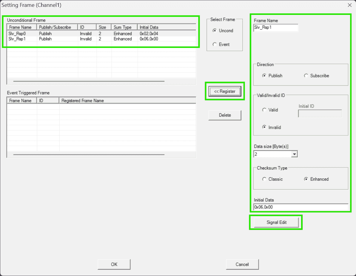
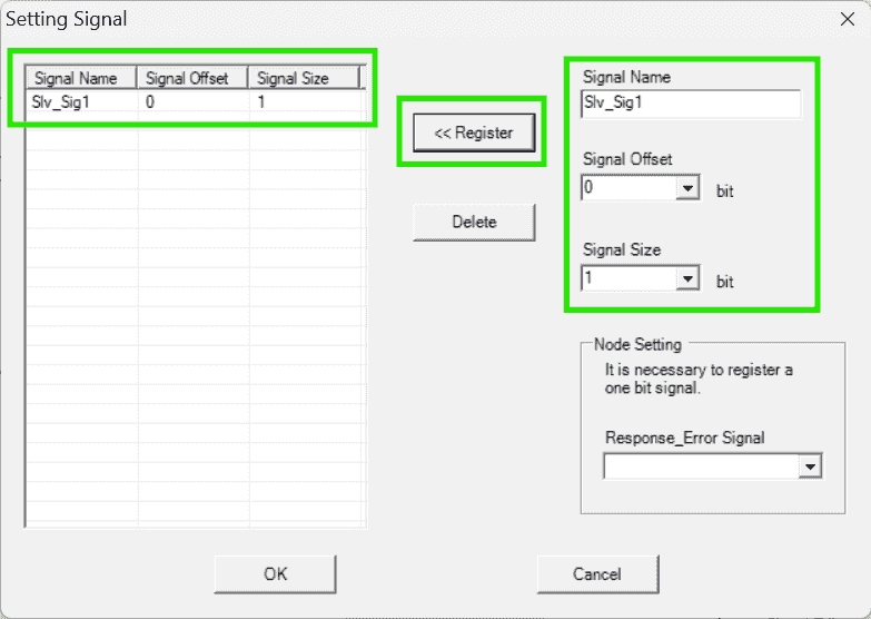
-
Both frame published by the slave required an
Response_Error_Signal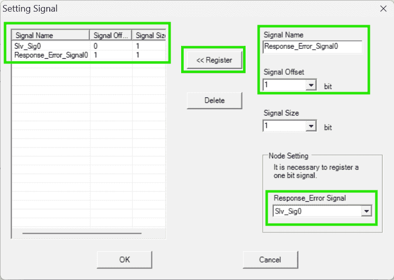
-
Save LIN Configurator project beside the
src/ -
Generate the driver source code into
src/r_riln3_lib/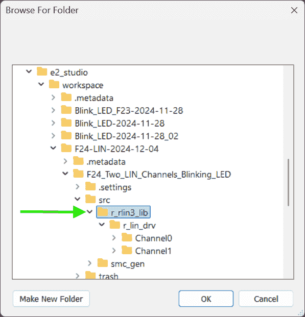
-
-
CS+ Builds Library
-
Actions:
-
Use CS+ to compile the driver source files:
-
Open the generated
.mtpjproject file. Each channel (Mater & Slave) has their own project: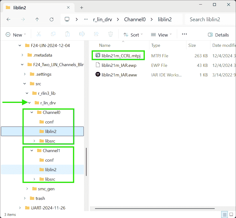
-
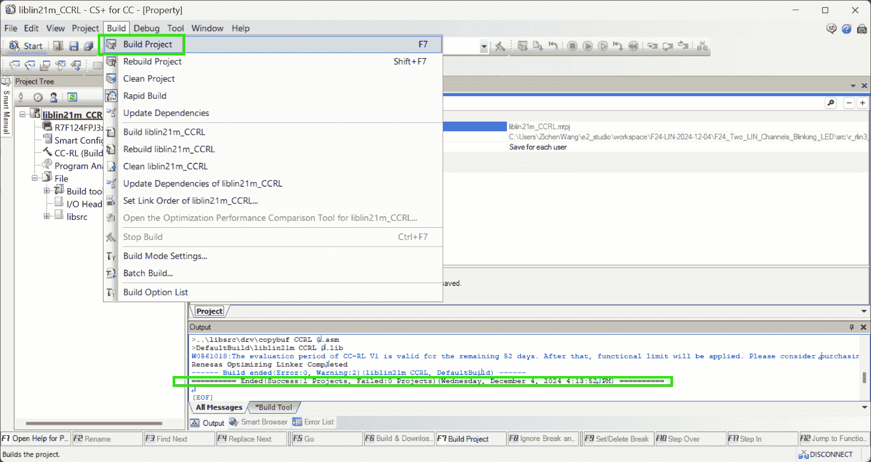
Build the CS+ project separately:
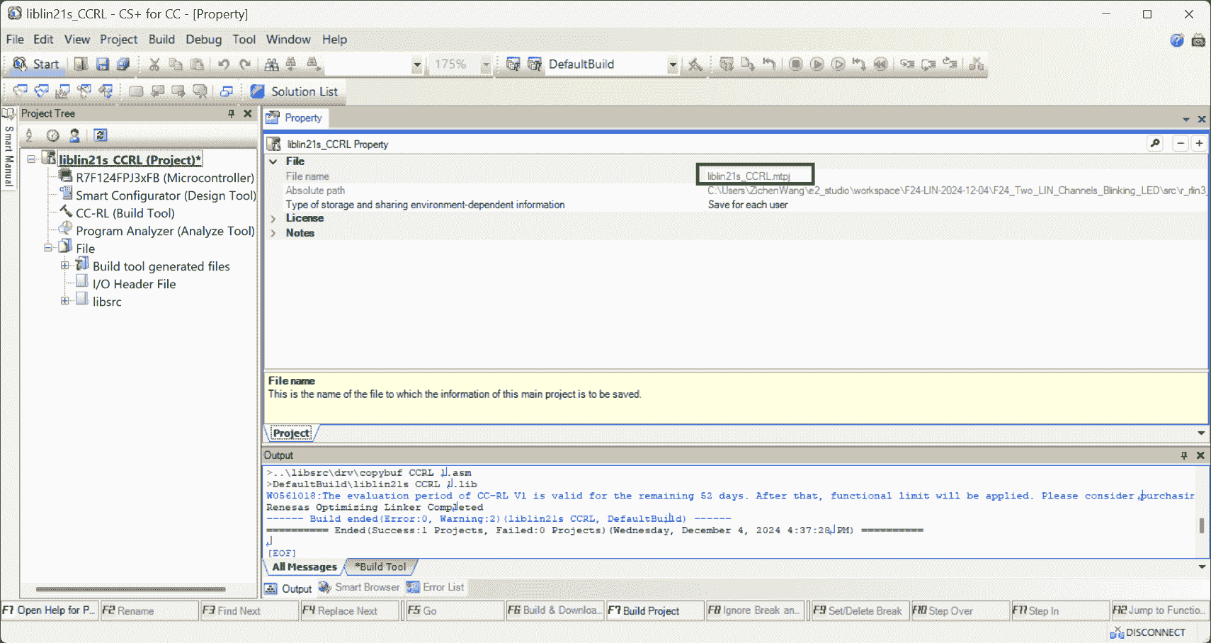
-
Library file
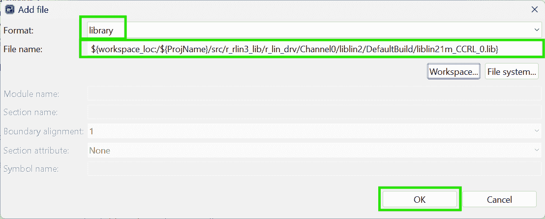
liblin21s_CCRL_0.libis generated r4-Ch5.
-
-
E2 Studio Compiler
-
Actions:
-
Go back the e2 Studio to configure the compiler: Include the LIN library.
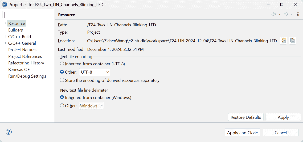
-
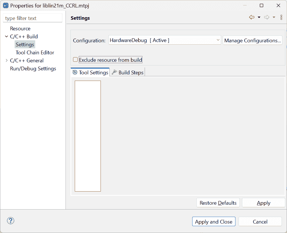
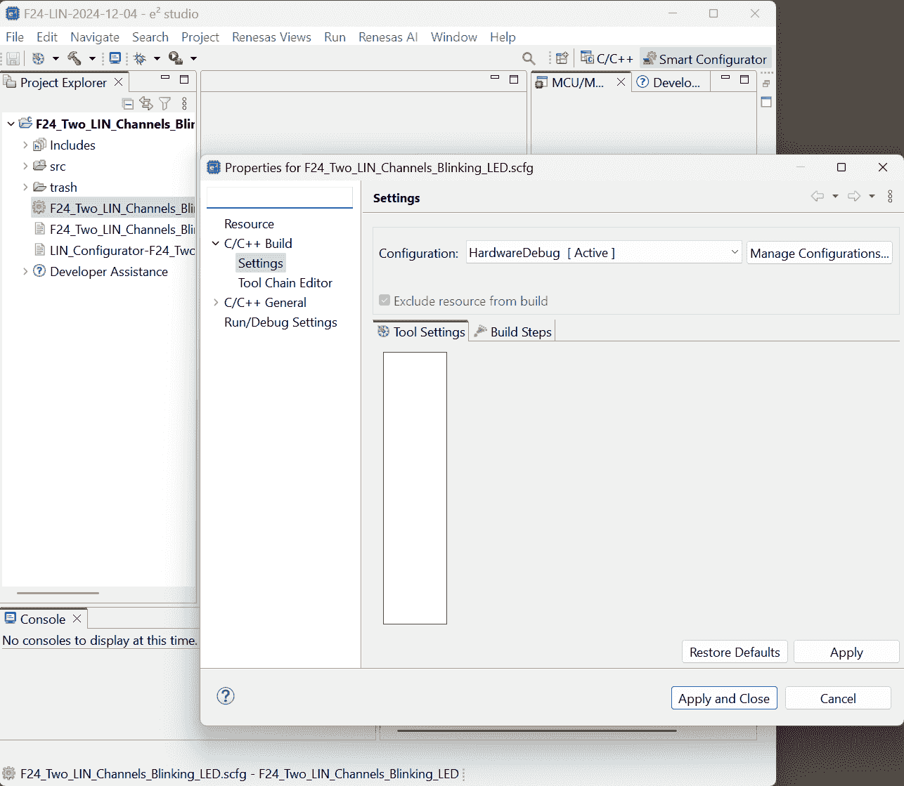
Open Building properties, encountering an error:
No property pages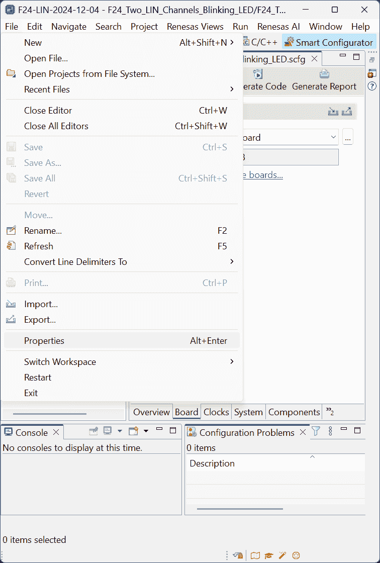
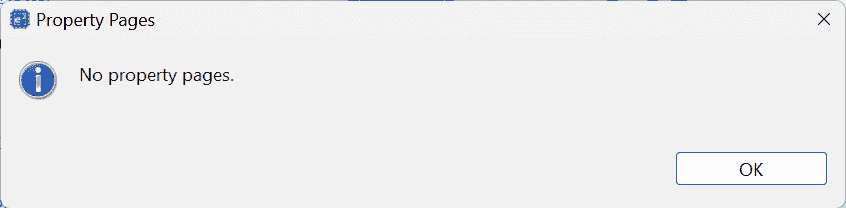
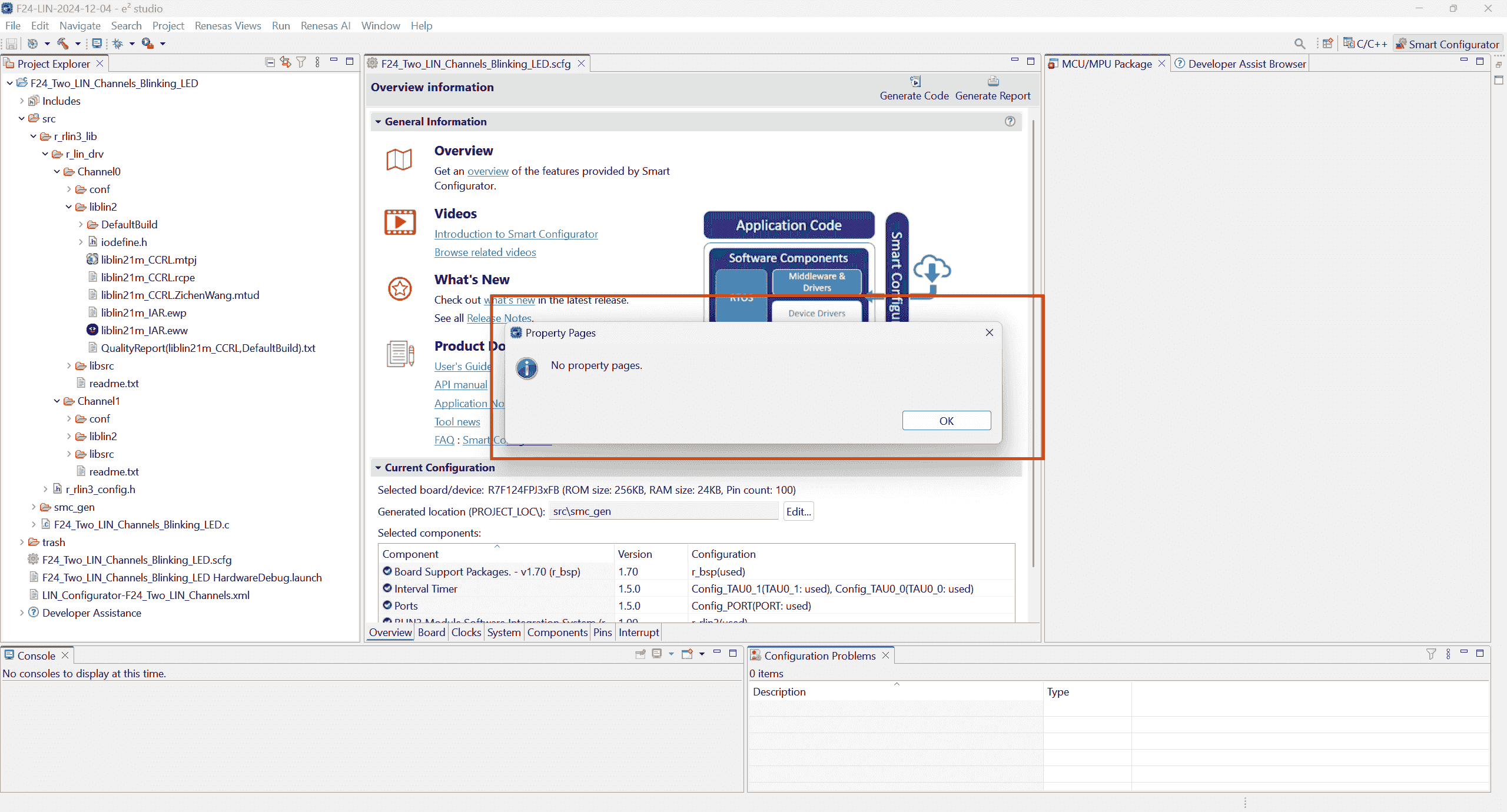
-
Maybe e2 studio should keep open, while I close it before. -
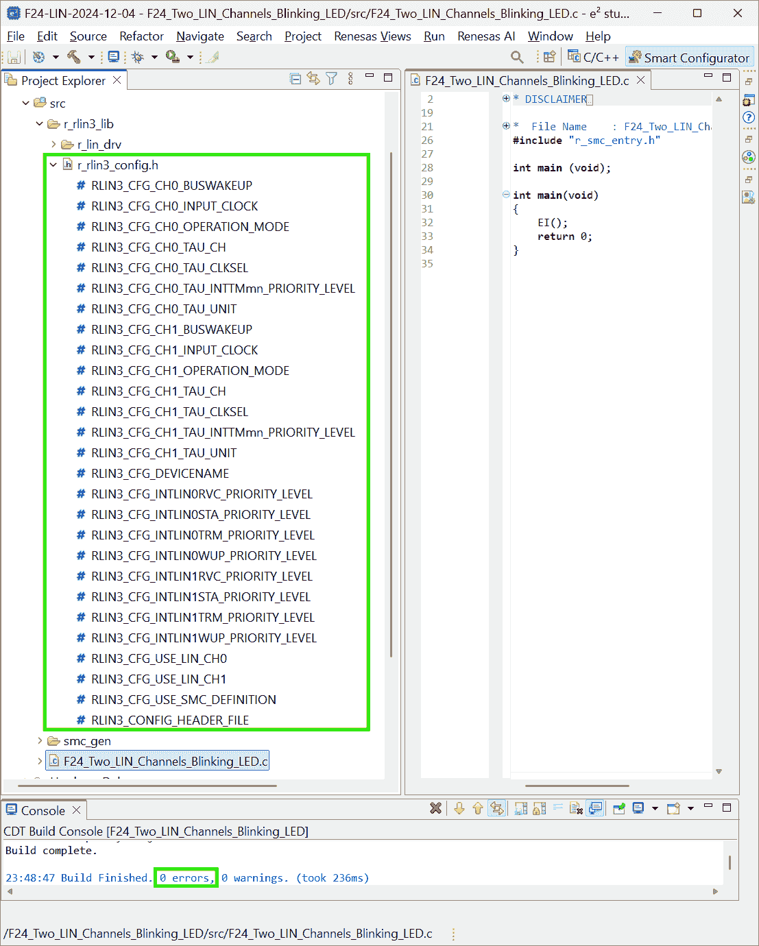
I generated the code again:
- Smcg generates code, and copy
r_rlin3_libto /src; - LIN Configurator generates code into
src/r_rlin3_lib - CS+ builds project.
Then, the e2 studio’s
File>Propertiescan be opened. - Smcg generates code, and copy
-
-
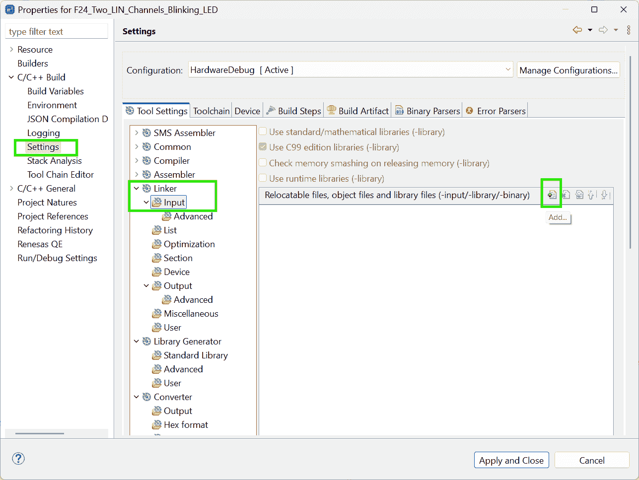
Add files: Relocatable files, object files, and library file setting
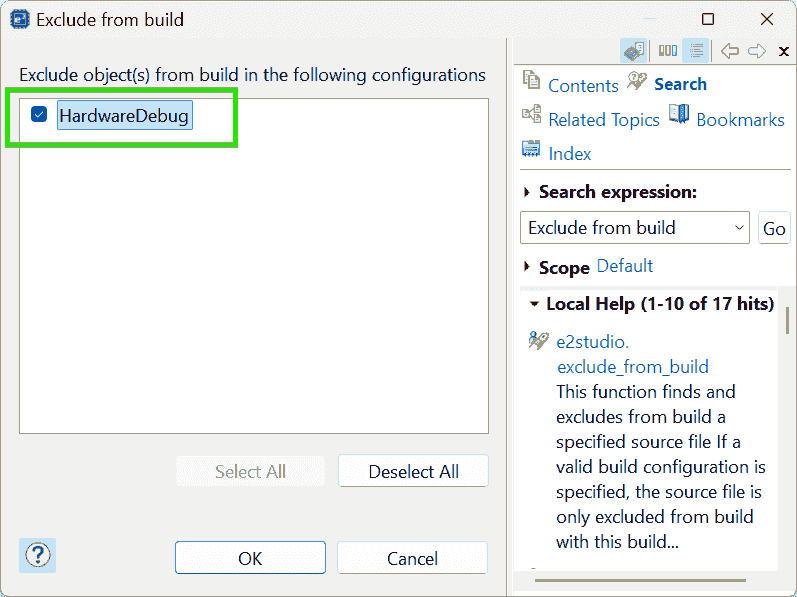
-
Exclude the “Driver source code” generated by the LIN Configurator from building process.
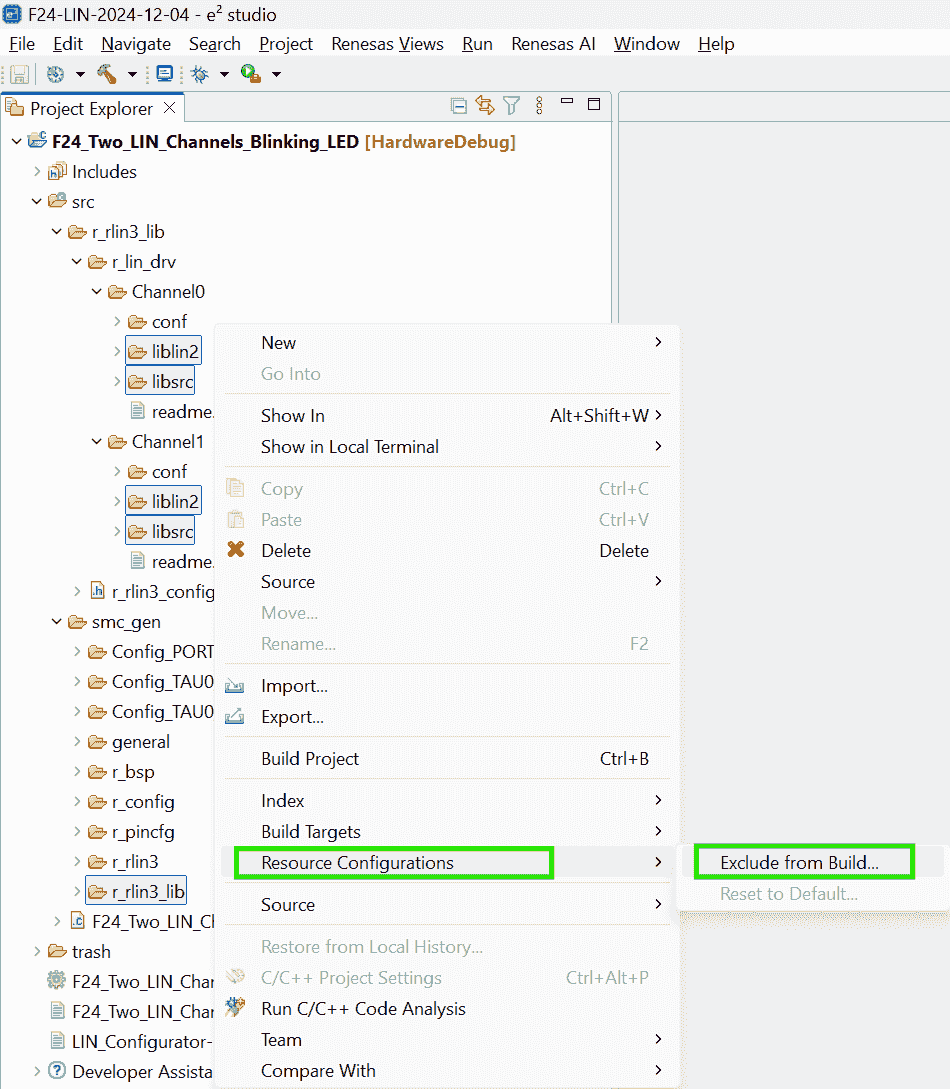
-
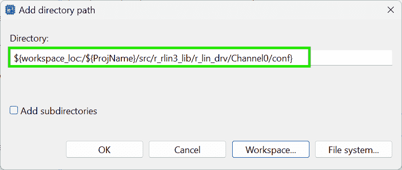
Add source files:
drv/conf/to Compiler-
The
File>Propertiesdosen’t appear again. -
After I canceled the excluding (un-check the “HardwareDebug” option), the
File>Propertiesstill doesn’t show up. -
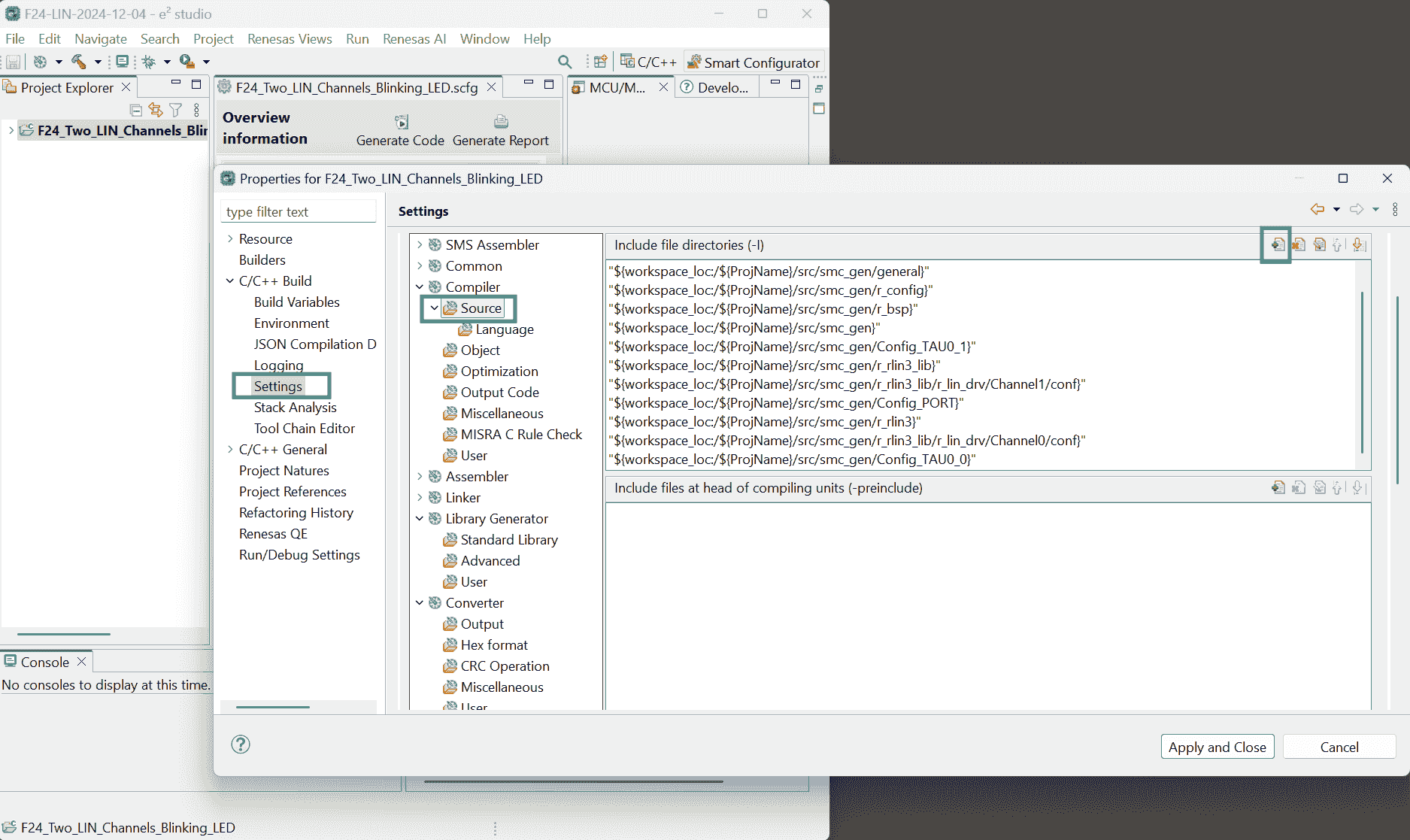
I re-generate the codes, but this time the properties missed many options:
-
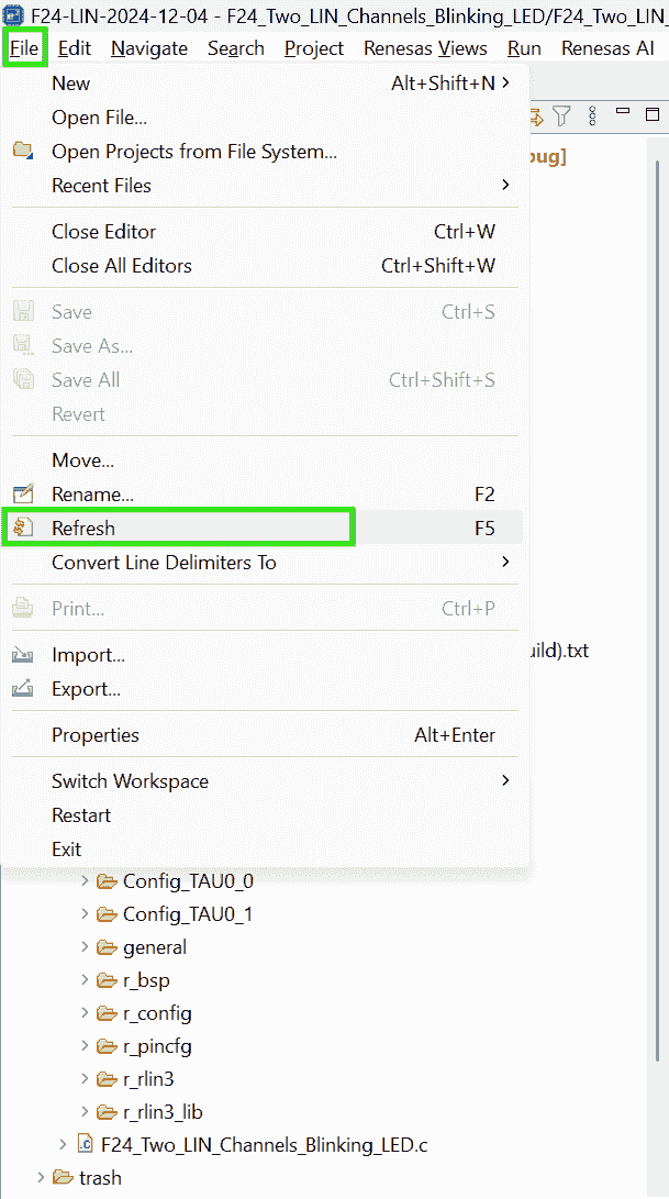
After clicking the Refresh, the properties are restored, but the Linker disappeared:
-
I closed the E2 studio, and reopen it, the
File>Propertiescan show up, although the “No property pages” pops again at first.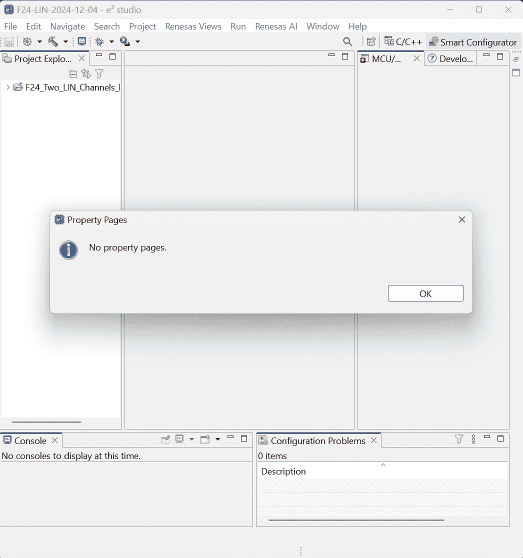
I have to select the project name!
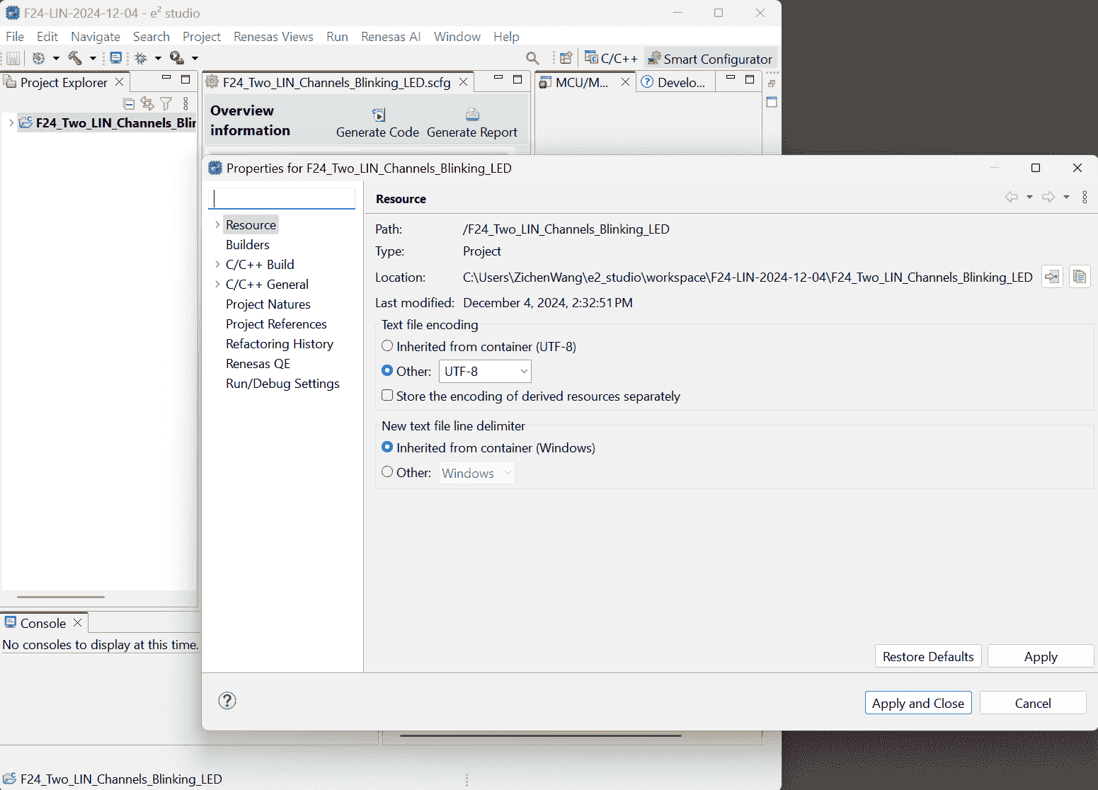
As I gradually Unfold the project level-by-level, the available properties are loaded gradually.
After I unfold the project folder, those properties disappeared again:
It seems that I have to Select the .smcg file to load settings.(Note: here, I have excluded those driver source code.)
-
-
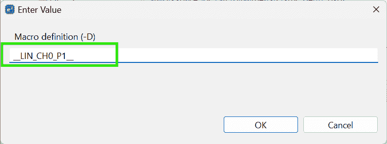
Add Macro Definition:
__LIN_CH0_P1__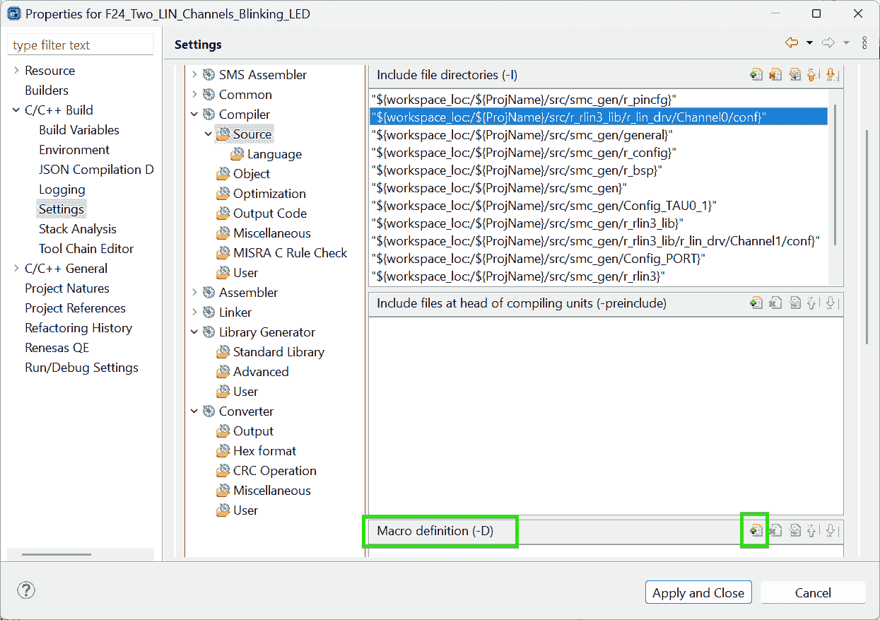
-
Memory Small model
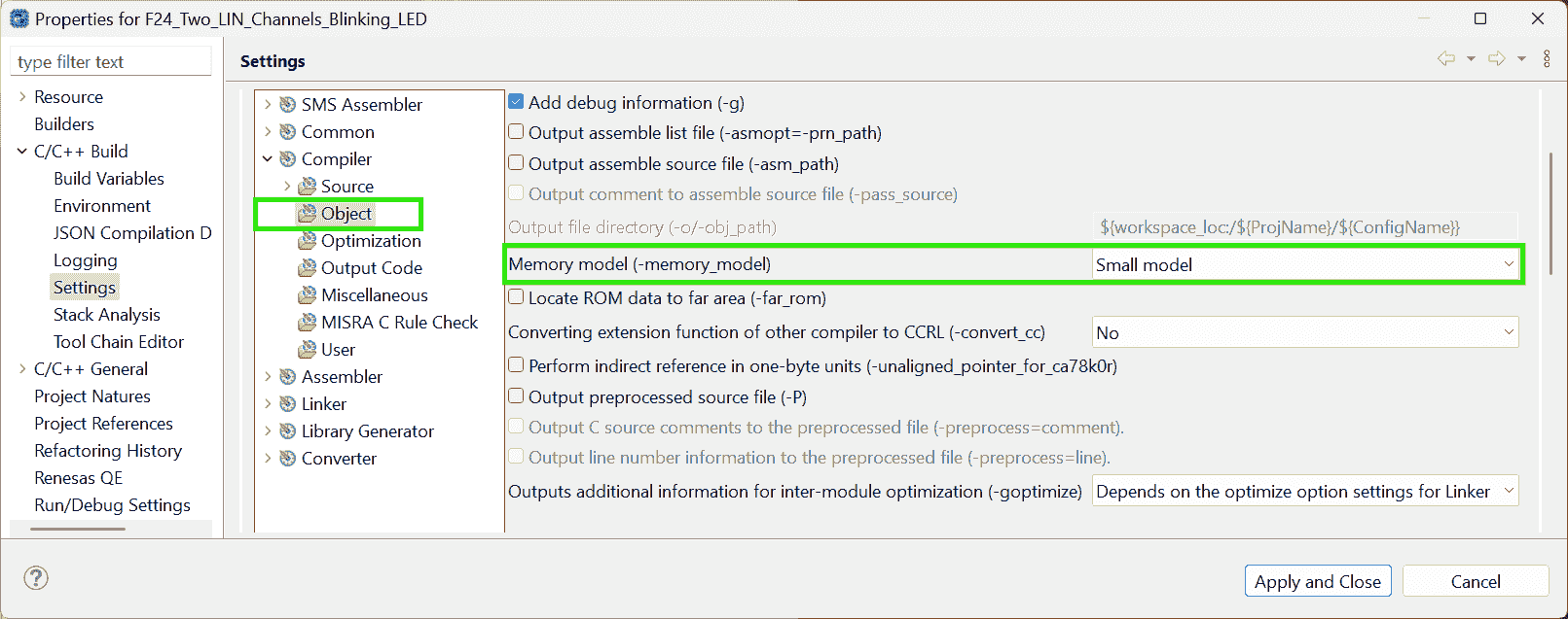
-
Re-Build Project:
-
-
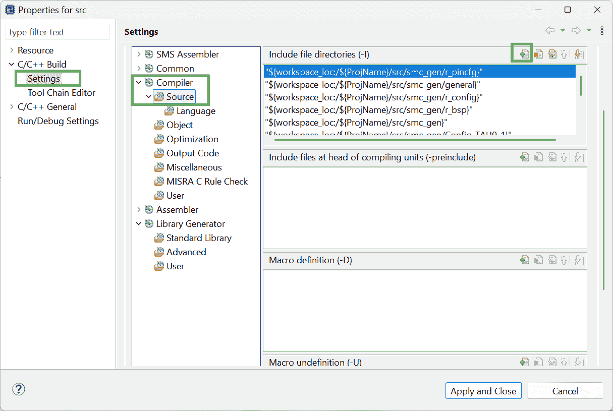
Use e2 Studio to configure the compiler for slave (Channel1)
-
Fold the Project andMake the project name selected. Or just Right click on the project name. -
File > Properties > C/C++ Build: Settings > Linker > Input > Add
liblin21s_CCRL_1.lib(built by CS+) -
Add source dir: Settings > Compiler > Source > Add
src/r_rlin3_lib/r_lin_drv/Channel1/conf/ -
Add Macro definition:
__LIN_CH1_P1_r2-Docs p29 -
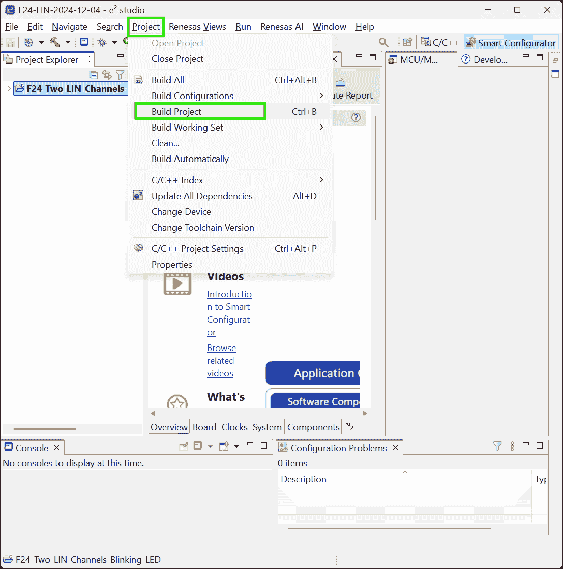
Right click on the project >
Build Project
-
-
Add User Code
Sample Code F13
References:
-
RL78 LIN sample code - Forum - RL78 MCU - Renesas Engineering Community
- Searched by
RL78/F13, F14 Group LIN Master Mode (RLIN3)in DDG
- Searched by
-
EK-RA6M4 sample project: [ERROR] Toolchain configured for project is not currently available. - Forum - RA MCU - Renesas Engineering Community
- Searched by
[ERROR] Toolchain configured for project is not currently available. Please add/enable toolchain through Renesas Toolchain Management or select a different toolchain for this project.in DDG
- Searched by
Notes:
(2024-12-18)
-
Open project
-
Actions:
-
Download the zip files r1-Forum: MASTER_LIN.zip; SLAVE_LIN.zip
-
Import existing projects > Select archive file: MASTER_LIN.zip > Finish
-
-
-
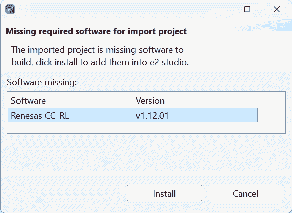
The sample code for F13 require CC-RL compiler, which however, cannot be installed:
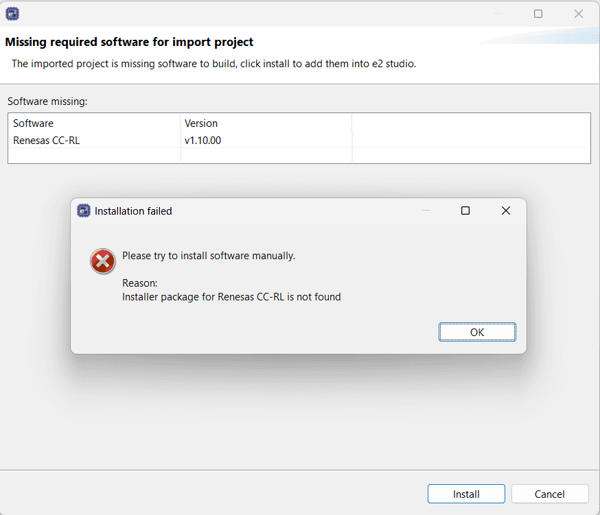
(2024-12-19)
-
Don’t find
make1 2 3 4 5 6 7 8 9 10Extracting support files... [ERROR] Toolchain configured for project is not currently available. Please add/enable toolchain through Renesas Toolchain Management or select a different toolchain for this project. 08:49:47 **** Incremental Build of configuration HardwareDebug for project MASTER_LIN **** make -r --output-sync -j20 all Cannot run program "make": Launching failed Error: Program "make" not found in PATH PATH=[C:/Renesas/e2_studio/eclipse//plugins/org.eclipse.justj.openjdk.hotspot.jre.full.win32.x86_64_21.0.3.v20240426-1530/jre/bin/server;C:/Renesas/e2_studio/eclipse//plugins/org.eclipse.justj.openjdk.hotspot.jre.full.win32.x86_64_21.0.3.v20240426-1530/jre/bin;C:\ProgramData\GCC for Renesas RL78 4.9.2.202201-GNURL78-ELF\rl78-elf\rl78-elf\bin;C:\ProgramData\LLVM for Renesas RL78 17.0.1.202409\bin;C:\Program Files (x86)\Common Files\Oracle\Java\java8path;C:\Program Files (x86)\Common Files\Oracle\Java\javapath;C:\Windows\system32;C:\Windows;C:\Windows\System32\Wbem;C:\Windows\System32\WindowsPowerShell\v1.0\;C:\Windows\System32\OpenSSH\;C:\Program Files\dotnet\;C:\Program Files\Tailscale\;C:\Program Files\Git\cmd;C:\Program Files\WireGuard\;C:\ProgramData\GCC for Renesas RL78 4.9.2.202201-GNURL78-ELF\rl78-elf\rl78-elf\bin;C:\ProgramData\LLVM for Renesas RL78 17.0.1.202409\bin;C:\Users\ZichenWang\AppData\Local\Microsoft\WindowsApps;C:\Users\ZichenWang\AppData\Local\Programs\Microsoft VS Code\bin;C:\Users\ZichenWang\.dotnet\tools;C:\Program Files (x86)\Nmap;C:\texlive\2024\bin\windows;C:\Renesas\e2_studio\eclipse] 08:49:47 Build Failed. 1 errors, 0 warnings. (took 47ms)However, my another project can be built successfully
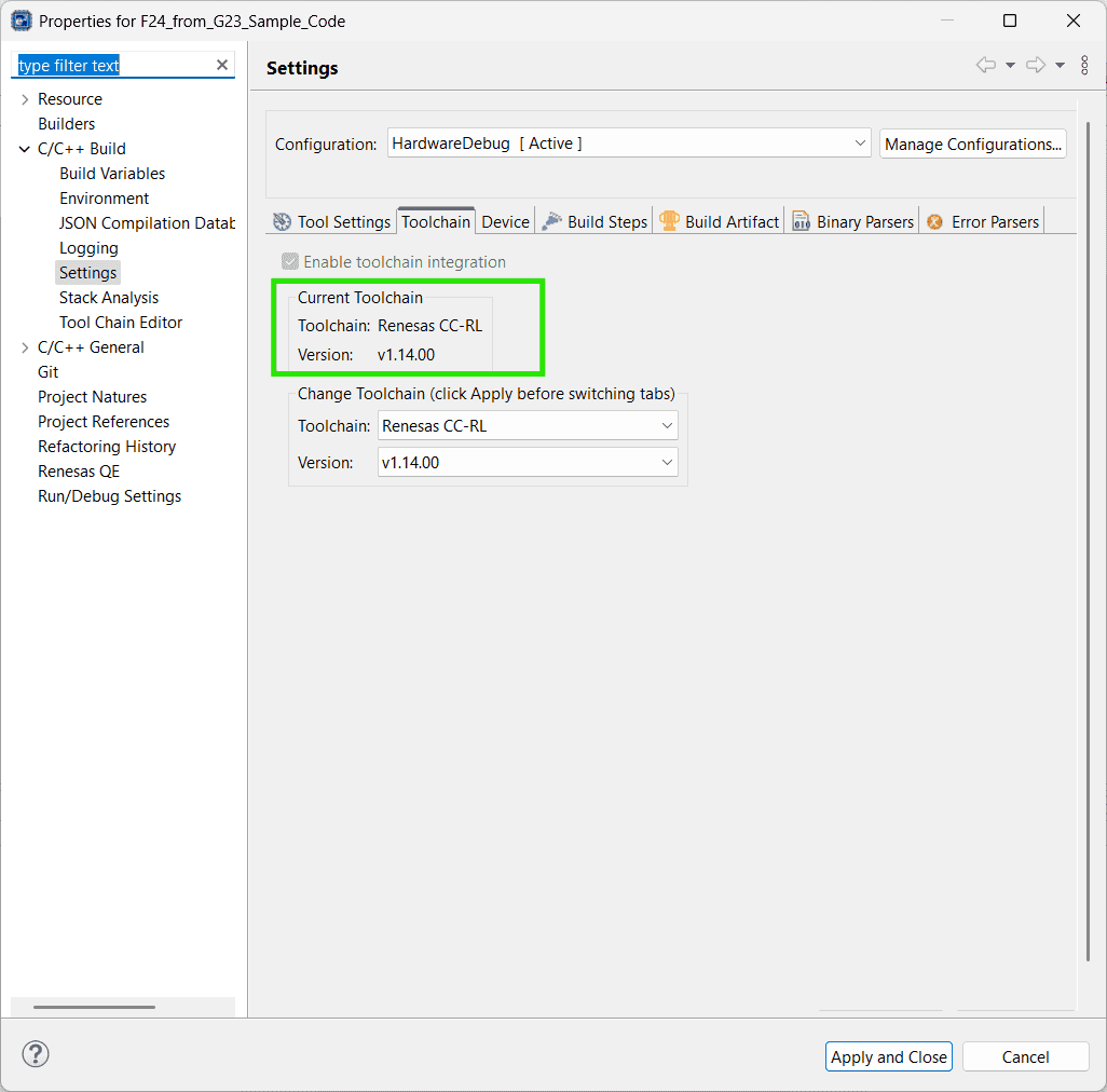
1 2 3 4 5 6Extracting support files... 09:01:55 **** Incremental Build of configuration HardwareDebug for project F24_from_G23_Sample_Code **** make -r --output-sync -j20 all Build complete. 09:01:55 Build Finished. 0 errors, 0 warnings. (took 157ms)Actions:
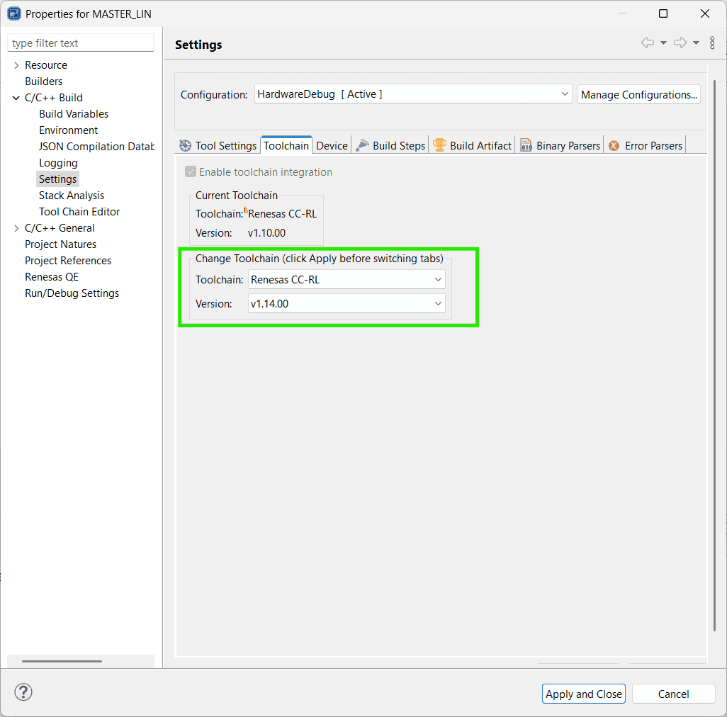
-
Check toolchain in File > Properties r2-Forum
The compiler
Renesas CC-RLwas set to an old version:v1.10.00. However, my compiler version is1.14.00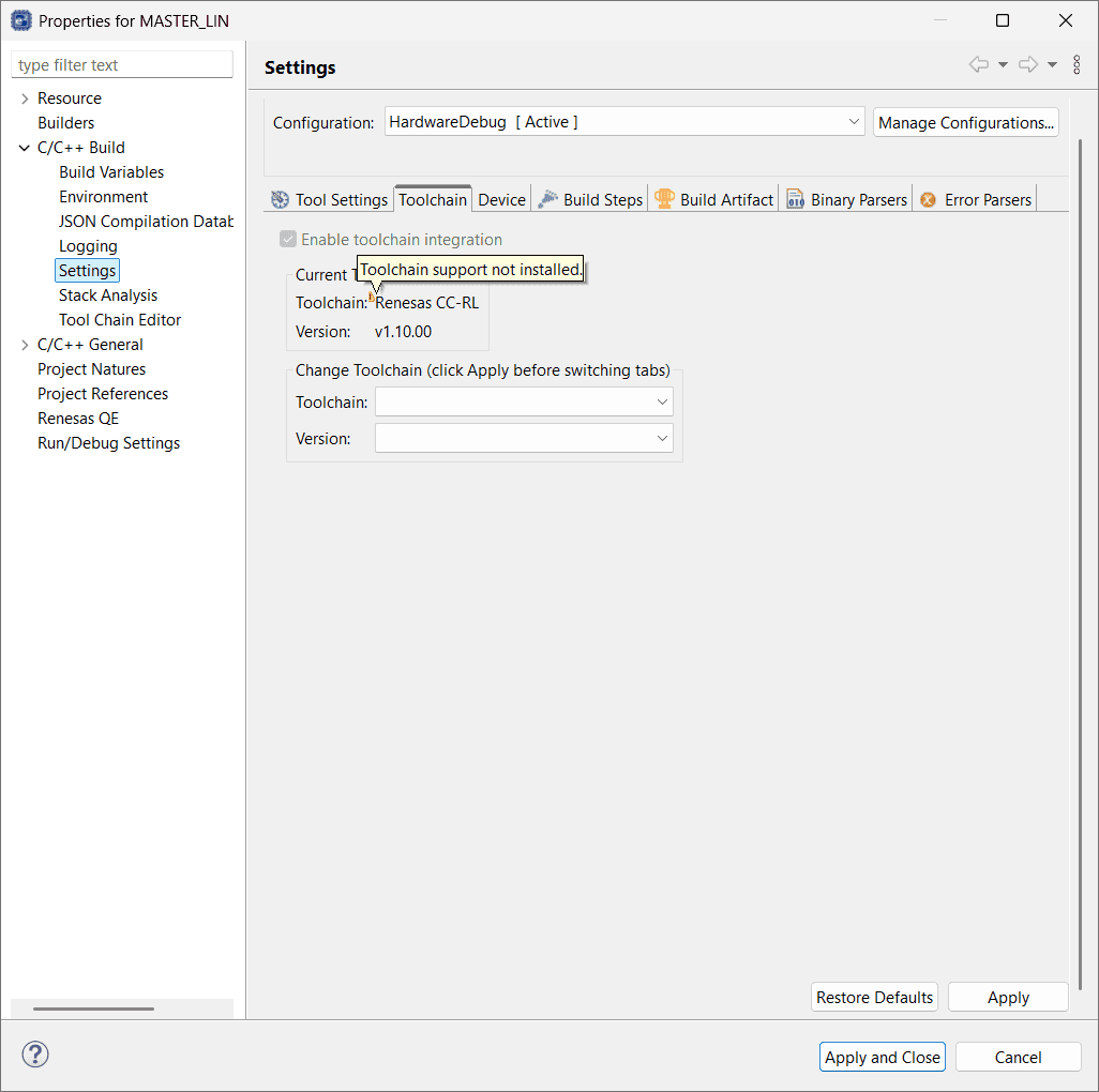
-
-
Exclude files from building
-
Actions:
-
Exclude
MASTER_LIN/src/MASTER_LIN.cfrom buildOtherwise, there will be an error:
Duplicate symbol "_main" in ".\src\MASTER_LIN.obj"Building failure messages
1 2 3 4 5 6 7 8 9 10 11 12 13 14 15 16 17 18 19 20 21 22 23 24 25 26 27 28 29 30 31 32 33 34 35 36 37 38 39 40 41 42 43 44 45 46Invoking Linker: MASTER_LIN.abs LinkerMASTER_LIN.tmp= -MAKEUD="C:\Users\ZichenWang\Downloads\Y-ASK-RL78F13-LIN\MASTER_LIN\HardwareDebug/MASTER_LIN_l.ud" -device="C:/Users/ZichenWang/.eclipse/com.renesas.platform_1435879475/DebugComp/RL78/RL78/Common/DR5F10BMG.DVF" -list -nooptimize -entry=_start -auto_section_layout -security_id=00000000000000000000 -debug_monitor=1FE00-1FFFF -user_opt_byte=FFFFE8 -ocdbg=84 -ocdtr -input=".\generate\cstart.obj" -input=".\generate\stkinit.obj" -input=".\src\MASTER_LIN.obj" -input=".\src\RLIN_driver.obj" -input=".\src\RLIN_driver_user.obj" -input=".\src\r_cg_cgc.obj" -input=".\src\r_cg_cgc_user.obj" -input=".\src\r_cg_intc.obj" -input=".\src\r_cg_intc_user.obj" -input=".\src\r_cg_port.obj" -input=".\src\r_cg_port_user.obj" -input=".\src\r_cg_wdt.obj" -input=".\src\r_cg_wdt_user.obj" -input=".\src\r_main.obj" -input=".\src\r_systeminit.obj" -library=".\MASTER_LIN.lib" -output="MASTER_LIN.abs" -debug -nocompress -memory=high -rom=.data=.dataR,.sdata=.sdataR -nomessage -nologo W0561018:The evaluation period of CC-RL V1 is valid for the remaining 37 days. After that, functional limit will be applied. Please consider purchasing the product. E0562300:Duplicate symbol "_main" in ".\src\MASTER_LIN.obj" Renesas Optimizing Linker Abort make: *** [makefile:111: MASTER_LIN.abs] Error 1 "make -r --output-sync -j20 all" terminated with exit code 2. Build might be incomplete. 13:04:51 Build Failed. 2 errors, 29 warnings. (took 1s.701ms) -
Exclude
MASTER_LIN/generate/hdwinit.asmfrom build:Otherwise, there is an error:
Duplicate symbol "_hdwinit" in ".\generate\hdwinit.obj"Building failure messages
1 2 3 4 5 6 7 8 9 10 11 12 13 14 15 16 17 18 19 20 21 22 23 24 25 26 27 28 29 30 31 32 33 34 35 36 37 38 39 40 41 42 43 44 45 46 47 48 49 50 51 52 53 54 55 56Extracting support files... 13:12:23 **** Incremental Build of configuration HardwareDebug for project MASTER_LIN **** make -r --output-sync -j20 all Invoking Library Generator: MASTER_LIN.lib Library Generator Completed LibraryGeneratorMASTER_LIN.tmp= -MAKEUD_LBG="C:\Users\ZichenWang\Downloads\Y-ASK-RL78F13-LIN\MASTER_LIN\HardwareDebug\MASTER_LIN_lbg.ud" -cpu=S3 -output=MASTER_LIN.lib -nologo Invoking Linker: MASTER_LIN.abs LinkerMASTER_LIN.tmp= W0561018:The evaluation period of CC-RL V1 is valid for the remaining 37 days. After that, functional limit will be applied. Please consider purchasing the product. -MAKEUD="C:\Users\ZichenWang\Downloads\Y-ASK-RL78F13-LIN\MASTER_LIN\HardwareDebug/MASTER_LIN_l.ud" E0562300:Duplicate symbol "_hdwinit" in ".\generate\hdwinit.obj" -device="C:/Users/ZichenWang/.eclipse/com.renesas.platform_1435879475/DebugComp/RL78/RL78/Common/DR5F10BMG.DVF" Renesas Optimizing Linker Abort -list -nooptimize -entry=_start make: *** [makefile:111: MASTER_LIN.abs] Error 1 -auto_section_layout -security_id=00000000000000000000 -debug_monitor=1FE00-1FFFF -user_opt_byte=FFFFE8 -ocdbg=84 -ocdtr -input=".\generate\cstart.obj" -input=".\generate\hdwinit.obj" -input=".\generate\stkinit.obj" -input=".\src\RLIN_driver.obj" -input=".\src\RLIN_driver_user.obj" -input=".\src\r_cg_cgc.obj" -input=".\src\r_cg_cgc_user.obj" -input=".\src\r_cg_intc.obj" -input=".\src\r_cg_intc_user.obj" -input=".\src\r_cg_port.obj" -input=".\src\r_cg_port_user.obj" -input=".\src\r_cg_wdt.obj" -input=".\src\r_cg_wdt_user.obj" -input=".\src\r_main.obj" -input=".\src\r_systeminit.obj" -library=".\MASTER_LIN.lib" -output="MASTER_LIN.abs" -debug -nocompress -memory=high -rom=.data=.dataR,.sdata=.sdataR -nomessage -nologo "make -r --output-sync -j20 all" terminated with exit code 2. Build might be incomplete. 13:12:23 Build Failed. 2 errors, 1 warnings. (took 352ms)
-
-
PWM
Principle
-
PWM 信号频率的理论上限是时钟频率的一半
-
References:
-
Supports:
(2025-06-03T14:26)
-
PWM 与时钟一样也是方波,由一次上升和一次下降组成。数字电路一般是由时钟的上升沿(或由下降沿)触发,所以生成一个 PWM 周期需要两个时钟周期:
-
双边沿触发的数字电路设计太复杂
-
电路被时钟边沿触发后,还需要经过计数器更新、比较寄存器 CCR,输出缓冲等运算,可能无法在半个时钟周期内(如果在上升沿触发,也就是在下降沿来临前),完成这些动作,实现有效跳变。
(2025-06-04T12:10)
- 不确定这是不是 “synchronization with f_CLK” mentioned in Page 415 of r1-HrdManual
-
-
f_PWM = f_CLK/2 时,PWM 分辨率为 2(计数器仅有 0,1 两种状态),没有应用价值r1-元宝
-
PWM 分辨率是自动重装载值 ARR,严格来讲是 1/(ARR+1)。ARR 是在一个 PWM 周期内的 时钟周期数量
-
ARR 计数值 = 3,分辨率是 1/4:
-
如果 CLK 频率是 72 MHz,不使用预分频器,ARR=3,则 PWM 频率是 72M/4 = 18M
-
脉宽调制:控制一个 pwm 周期内高电平和低电平的比例。 时钟信号的占空比是 50%,高低电平各占一半,而 PWM 生成的方波占空比可以在 0% 和 100% 变化,通过设置计数器的最大值。
-
-
-
一个 PWM 周期内通常不允许大于两次电平跳变,所以无法实现电平为 010100 的一个 PWM 周期r3-Gemini
-
ARR = 6
-
-
加预分频器是为了避免超出计数器的最大计数值r2-元宝
- 主时钟频率 72MHz,目标 PWM 频率 1kHz,不使用 Prescaler,则 ARR 是 71,999,如果使用 16 位的计数器(最大计数值是 65,535,还未数到 71,999,就复位到0了。
-
预分频器无法增加占空比分辨率,即缩小占空比的最小步进
-
主时钟频率 72MHz,目标 PWM 频率 100 kHz,不使用 Prescaler,则自动重装载值是 720,如果使用 16 位的计数器(最大计数值是 65,535,但有效计数区间只是 720,占空比的分辨率只有 1/720,没有充分利用 16 位计数器的理论分辨率 1/65535.
如果使用 Prescaler = 2, ARR 会进一步减小到 360,占空比分辨率是 1/360。为了增加分辨率,可以增加主时钟频率。
-
-
-
-
PWM 信号的频率不会影响电机转速
-
Supports:
- PWM 信号频率影响稳定性和损耗r1-元宝
-
Renesas Configure
Issues:
Notes:
-
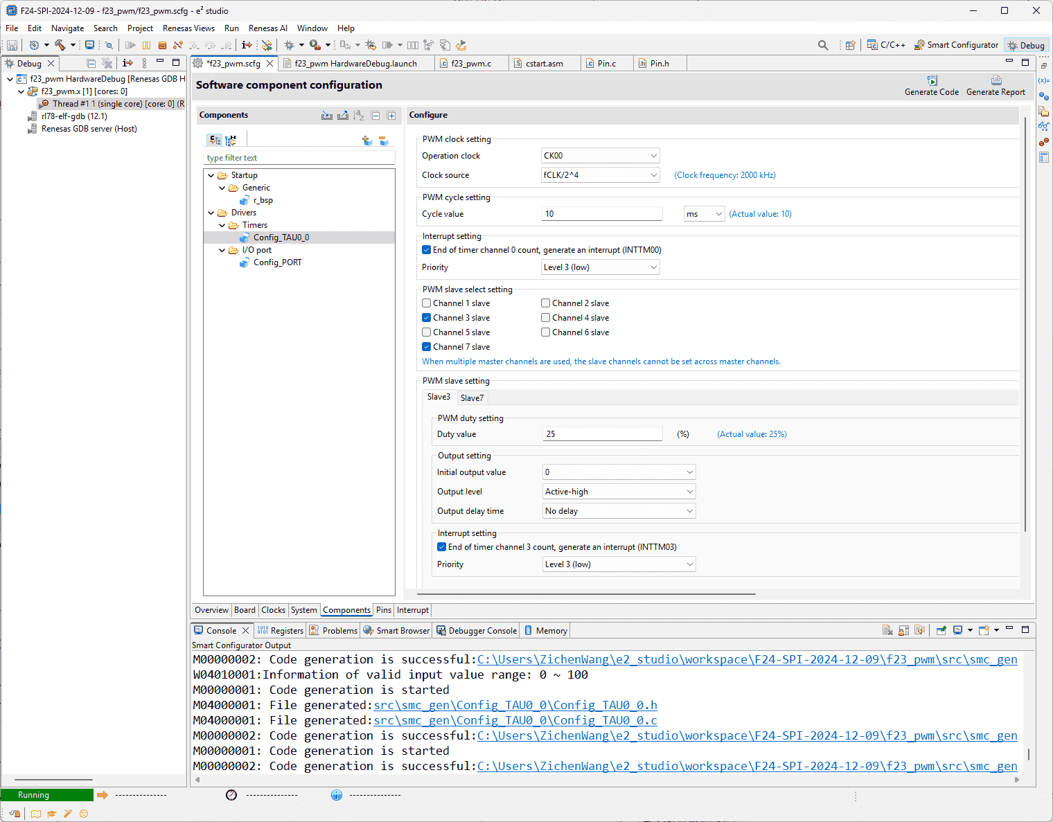
Configurations for One PWM with Two Channels in Smart Configurator
-
Supports:
-
module
PWM OutputTwo channels have different duty of cycles:
-
-
-
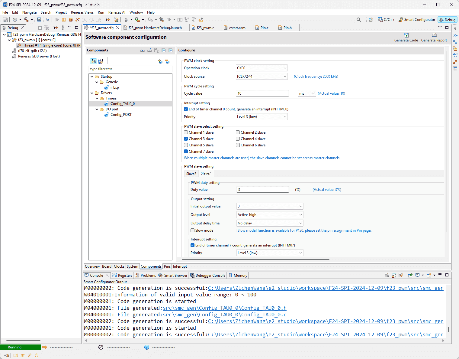
Configure Two PWM with Different Frequencies
-
Supports:
(2025-06-03T09:25)
- Pump and solenoid requires different-frequency PWM signals.
-
-
Renesas RL F23 Hardware
-
References:
-
Supports:
-
TAU Registers (Page 372 in r1)
-
Timer Count Operation Mode (Page 417)
-
-
-
Minimum Code
-
References:
-
4.2.9 PWM Output - Smart Configurator User’s Manual: RL78 API Reference
- Searched by
PWM smart configurator rl78in Renesas search
- Searched by
-
4.2.9 PWM Output - Smart Configurator User’s Manual: RL78 API Reference
-
-
RL78/G13 Timer Array Unit(PWM Output) CC-RL - Docs
- Searched by
Renesas rl78 timer pwmin DDG
- Searched by
Supports:
(2025-05-22T15:11)
-
6 functionsr1-Docs:
1 2 3 4 5 6R_{Config_TAUm_n}_Create R_{Config_TAUm_n}_Start R_{Config_TAUm_n}_Stop R_{Config_TAUm_n}_Create_Userinit r_{Config_TAUm_n}_channeln_interrupt r_{Config_TAUm_n}_channelp_interrupt -
Example code of F13r2-Docs
-
High-level understanding
- Duty-cycle determines the overall voltage. If the duty-cycle is 50% and the power supply is 12V, the equivalent power supply is 6V.
F24 LED
Problems:
- Different duty cycle corresponds to different level of brightness, as essentially the voltage varies alongside the duty cycle.
Algorithm Design
Software Design
(2025-05-29T12:07)
-
Configurations:
-
References:
-
Supports:
-
Clock, Debugger, Pin 67 out for LED2, Master and Slave
-
周期方波信号:由定时器 TAU0 的 channel 0 (Master) 的中断产生
-
比较器:由定时器 TAU0 的 channel 0 (Slave) 的中断产生
-
-
Actions:
-
main.c1 2 3 4 5 6 7 8 9 10 11 12 13 14#include "r_smc_entry.h" void main (void); void main(void) { R_Config_TAU0_0_Start(); /* TAU00,TAU01 operation enable */ EI(); while (1U) { HALT(); /* Waiting interrupt */ } } -
Config_TAU0_0_user.c1 2 3 4 5 6 7 8 9 10 11 12 13 14 15 16 17 18 19 20 21 22 23 24 25 26 27 28 29static void __near r_Config_TAU0_0_channel0_interrupt(void) { /* Start user code for r_Config_TAU0_0_channel0_interrupt. Do not edit comment generated here */ static uint8_t s_tm00_count = 0U; /* INTTM00 interrupt times counter */ uint16_t temp_duty = 0U; /* Duty factor calculation */ if (250 == (++s_tm00_count)) /* Update the duty cycle per 500ms */ { s_tm00_count = 0U; /* Interrupt counter reset */ P5 ^= 0x04; /* Invert LED2 */ temp_duty = TDR01; /* Read the current duty cycle (duty factor) setting */ if (temp_duty <= (_E100_TAU_TDR01_VALUE / 9)) { /* If current duty cycle is 90% (duty factor is 10%), */ temp_duty = _E100_TAU_TDR01_VALUE; /* Set duty cycle to 10% (duty factor to 90%) */ } else { /* Increase duty cycle by 20% (decrease duty factor by 20%) */ temp_duty -= ((_E100_TAU_TDR01_VALUE / 9) * 2); } TDR01 = temp_duty; /* Update duty cycle (duty factor) */ } else { ; } /* End user code. Do not edit comment generated here */ }
-
-
-
Test Case
Test Report
ADC
Problems:
- The api code generated by “Code Generator” in CS+ is different from the code generated by “Smart Configurator”.
References:
-
ADC Configuration - Forum - RL78 MCU - Renesas Engineering Community
- Searched by
renesas rl78 adcin DDG
- Searched by
-
ADC Sample code - Forum - RL78 MCU - Renesas Engineering Community
- Found in s1
-
RL78/G13 A/D Conveter(Software Trigger and Sequential Conversion Modes) CC-RL - R01AN2581EJ0200 Rev. 2.00
- Searched by
renesas rl78 ad conversionin DDG
- Searched by
-
RL78/G23 A/D Converter (Scan mode) - Renesas
- Found in s2
-
Web simu
- Found on MCU Simulator Online
Practices:
(2025-01-10)
-
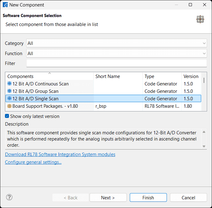
Create>Start>Get_ValueResultr1-ForumThere are only 3 api functions for consideration in the generated source file:
Config_S12AD01.c.1 2 3 4 5 6 7 8 9 10 11// R_Config_S12AD01_Create() // R_Config_S12AD01_Start() // R_Config_S12AD01_Stop() // R_Config_S12AD01_Get_ValueResult() -
ADC needs to be executed inside interruption r2-Forum
(2025-01-30)
- This is not necessary. The
R_Config_S12AD0_Get_ValueResult(ADCHANNEL0, &g_result_buffer);can just put in thewhile(1U)loop.
- This is not necessary. The
-
RL78/G13 r3-Manual has different code from F24.
RL78/G23 r4-Manual code is not searched yet.
Online simulator r5-Simu includes several AD projects.
-
G23 code on web simu used
ADCSregister, which doesn’t exist in F23 project.
(2025-01-30)
-
I don’t set up the interrupt function, and only write the
main.c-
But the
~_Startis necessary before~_Get_ValueResultto enable conversion. -
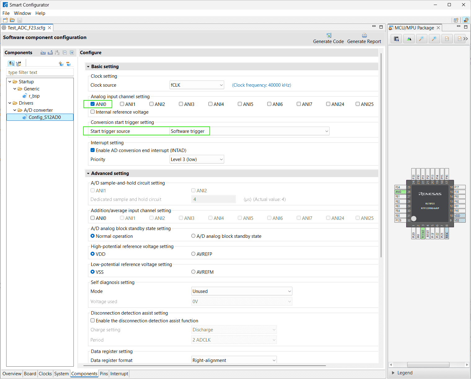
Actions:
-
Smcg select: Software trigger
-
1 2 3 4 5 6 7 8 9 10 11 12 13 14 15 16 17 18 19 20// main.c #include "r_smc_entry.h" uint16_t g_result_buffer = 0U; void main(void); void main(void) { g_result_buffer = 0U; /* Initialize result buffer */ R_Systeminit(); EI(); while (1U) { R_Config_S12AD0_Start(); R_Config_S12AD0_Get_ValueResult(ADCHANNEL0, &g_result_buffer); } }If the value is
0x3328d, calculting the source voltage according to the: Voltage Divider Calculator$$ \begin{aligned} \frac{x}{4096} \times 5 = y \\\ y = \frac{V_S \times R_2}{R_1 + R_2} \\\ = \frac{V_S \times 47}{47 + 18} \\\ \end{aligned} $$-
12-bit A/D converter: 4096 levels
-
Reference voltage is VDD = 5V to the MCU
-
$R_2$ = 18K, $R_1$ = 47K
$$ \begin{aligned} y = \frac{3328}{4096} \times 5 = 4.0625 \\\ V_S = 4.0625 \times 65 / 18 = 14.67 \end{aligned} $$14.67 + 0.7 = 15.37 V, which is close to Power supply 15.2 V.
-
IAR IDE
Blinky LED
Problems:
- Use IAR IDE to implement a binking LED project for RL78 F23
Issues:
References:
-
Create a blinky project from scratch (IAR™) - YouTube - RenesasPresents
- Searched by
renesas IAR blink LED projectin DDG
- Searched by
-
RL78 Smart Configurator User’s Guide: IAR
- Seached by
renesas R20AN0581in DDG - Mentioned in RL78/G23 - Renesas Electronics Corporation
- Searched by
renesas RL78 IAR blink LED projectin DDG
- Seached by
- Using Smart Configurator with IAR Embedded Workbench for RL78 (2/2) - Creating an EWB Project for Smart Configurator
-
Basic debugging - IAR
- Searched by
IAR debugg settingsin DDG
- Searched by
-
C-SPY® Debugging Guide for the Renesas - IAR
- Searched by
IAR debug settings for renesas e2 litein DDG
- Searched by
-
IAR Embedded Workbench Overview - Part 1 - YouTube - IAR
- Searched by
IAR debugging demostrationin DDG videos
- Searched by
Practices:
(2025-04-08)
-
✅ Building project with Smart Configurator + IAR
-
Supports:
- Create Smart Configurator project under the IAR project folder ➔ Generate Code (.ipcf and .ewp same dir)r3-Video
-
Actions:
-
Build Errors:
1 2Error[Lp004]: actual size (0x5) exceeds maximum size (0x4) for block "OPT_BYTE" Error[Lp004]: actual size (0x10) exceeds maximum size (0xa) for block "SECUR_ID"
(2025-04-10)
-
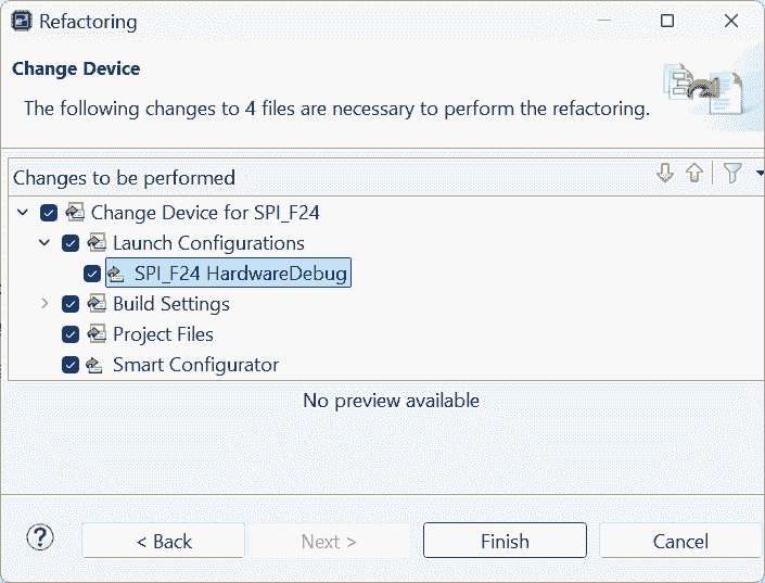
Set the Device to matched MCU modelr6-Ytb

-
-
Results:
- Build succeeded.
-
(2025-04-11)
-
✅ Debug with IAR

(2025-04-21T16:40:09)
-
✅ IAR blink LED
-
Supports:
-
MCU_V_D_IN1is high side pin. -
Same code can blink the LED during debugging in CS+, however debugging with IAR doesn’t result in LED blinking.Check pin definition and ensure its reference is correct.1 2 3 4 5 6 7 8 9 10 11 12 13 14 15 16 17#include "r_smc_entry.h" void delay(long d){ while(d--); } int main(void) { while(1) { PIN_WRITE(MCU_V_D_IN1) = 0; delay(500000); PIN_WRITE(MCU_V_D_IN1) = 1; delay(500000); } return 0; }
-
-
Migrate from CS+
Problems:
- How to port our previous Renesas CS+ projects to IAR projects
References:
-
RL78 Software Porting Guide - Renesas Electronics Corporation
- This guide is for porting between different MCUs.
- Searched by
How to port Renesas CS+ projects to IAR projectsin DDG
-
Migration guide: Migrating from the CS+ CA78K0R toolchain for RL78 to IAR Embedded Workbench® for RL78 - IAR
- Found in s1
-
Porting the code from CC-RL compiler to IAR
- Searched by
port CS+ to IARin Renesas
- Searched by
Notes:
(2025-04-16T11:06:03)
-
IAR has a tool:
Convert to IAR for RL78r2-guide-
Supports:
- There is only “Project type” selectable: “CubeSuite for RL78”
-
Actions:
- Using default settings leads to a compilation error
-
Build Options
Problems:
- Compilation options settings
Issues:
- Optimization level
- Error
Notes:
(2025-04-22)
-
Optimization level:
-
Supports:
- Do not apply optimization for step-by-step debugging
-
Actions:
- Project -> Options -> C/C++ Compiler -> Level: None
-
(2025-04-24T10:17:31)
-
Error:
-
Supports:
-
Debug the RLIN3 example project
-
Pop-up window:
1 2 3 4 5 6 7 8 9 10 11.----------------------------------------. |E2LITE × | | | | Target power mode mismatch | | ? | | Press YES to try again. | | | | Pressing NO will end debug session. | | | | Yes No | '----------------------------------------' -
As shown in title of “E2Lite Hardware Setup (R7F124FPJ)”
- The F23 MCU isn’t compatiable with the debugger setting for F24 MCU.
-
-
Actions:
- By only connecting the debugger to the F24 development board, the program can be downloaded and debugged without needing to separately power the development board (using the default hardware setup).
-