相机旋转
(2022-05-22)
坐标系旋转是 point 旋转的逆(点逆时针旋转θ 等效于坐标系顺时针旋转θ)
点P在初始坐标系下的坐标为 Pₒ,在目标坐标系下的坐标为 Pₜ, 从 Pₒ 到 Pₜ 中间是 target 坐标系在 origin 坐标系下的表示(方向向量)[𝐫ₓ 𝐫ᵧ]ᵀ:
$$ \begin{bmatrix} xₜ \\ yₜ \end{bmatrix} = \begin{matrix} rₓ: \\ r_y: \end{matrix} \begin{bmatrix} a₁ & b₁ \\ a₂ & b₂ \end{bmatrix} \begin{bmatrix} xₒ \\ yₒ \end{bmatrix} $$
-
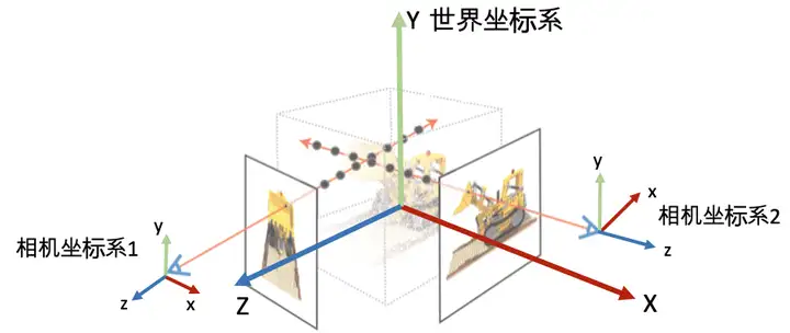
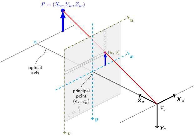
横着看:行向量 (a₁,b₁) 是 target 系的 x 轴在 origin 系下的方向向量, (a₂,b₂) 是 target 系的 y 轴在 origin 系下的方向向量。 例如,下图中 origin 系是 world,target 系是 camera:
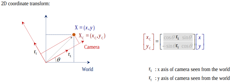
- Original 坐标$[^x_y]$做线性组合,变换到了 Target 坐标系$[^{x_c}_{y_c}]$。
-
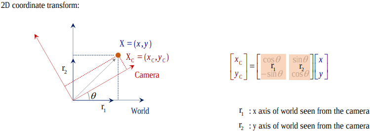
竖着看:列向量 (a₁,a₂) 是 origin 系的 x 轴在 target 系下的方向向量, (b₁,b₂) 是 origin 系的 y 轴在 target 系下的方向向量。
-
综上,旋转矩阵 R (in w2c) 横着看就是 camera (target) 系在 world 系下的表示,竖着看就是 world (original) 系在 camera 系下的表示。
- (2023-11-05) 所以通过转置就可以把 R in w2c 切换成 R in c2w。 但是要把 w2c 变成 c2w,需要对 [R|t] 整体求逆。
-
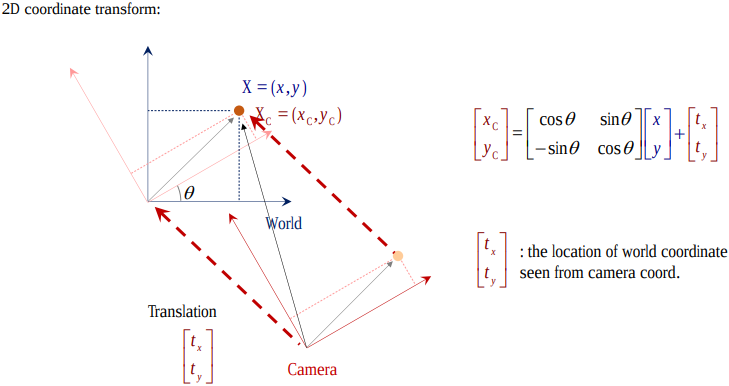
欧几里得变换 [R T]:旋转矩阵 R 加平移向量 T,把点在 origin 系的坐标变成在 target 系下的坐标,或者说把 origin 系变换成 target 系。
For example, w2c as below.
-
先旋转后平移:点在 origin (world) 系下的坐标先经过 target (camera) 系在 origin 系下的方向向量 R 的线性组合,即 投影(做内积)到了一个与 target 系坐标轴都平行的新坐标系(虚线)下, 再加上一段平移向量 T,从而使新坐标是以 target 系的原点开始,所以 T 就是 origin 系的原点在 target 系视角下的坐标。
-
This process is expressed by [R|t]. Conversely, [R|t] denotes rotation first then translation.
-
(2024-01-09) 𝐭 is coordinate measured in the target space, because 𝐭 is simply added onto the target coordiantes without “recombination” of the elementary vectors in a basis. Therefore, 𝐭 is the original center seen from the target space.
-
-
或者先平移后旋转:origin (world) 系下的坐标先减去 target (camera) 系原点在 origin 系下的坐标 C, 变到了一个新坐标系下(其原点与 target 系原点重合), 再旋转到与 target 系各轴重合;所以 C 就是 camera 光心在 world 系下的坐标。
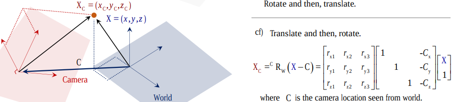
- In this case, R and T can’t be written as an augmented matrix, but separate matrices.
- If the given point’s coords are world coords, then apply [R|t]. While if point is already in camera space, only apply [R].
-
-
可借助 vanishing points (待定系数)来求旋转矩阵(This point is at infinite but finite in image.) Camera Projection Matrix-UofMinnesota
透视投影
(2022-05-08)
透视投影(内参矩阵K)把 camera space 下的坐标投影到焦平面上,X 除以 Z 乘以 f(即以 f/z 为系数对 x,y 做一个缩放)。 如果焦距(焦平面距离) f 是常数,那就直接是与 z 成反比。
- (2024-01-31) 所以 “z” 代表的是 “Zoom” 缩放:近大远小. Ray Marching for Dummies! - Ytb - The Art of Code
(这里坐标都是绝对值,不考虑坐标系的选取)
- 因为景物是 倒置 的,所以像素坐标系的 y 轴是向下的?
若采用齐次坐标(用矩阵表达除法), 对 [X,Y,Z] 做透视投影得到的是 [fX, fY, Z],则 [u, v, 1] = [fX/Z, fY/Z, 1]。 再以像素尺寸 dx,dy 缩放并加上(+)光心坐标 cx,cy,把原点从光心移到左上角(像素系的v轴是朝下的,所以还需要加负号?),就变到了像素坐标系下:
$$ \begin{bmatrix} \frac{f}{dx} & 0 & cₓ \\ 0 & \frac{f}{dy} & c_y \\ 0 & 0 & 1 \end{bmatrix} \begin{bmatrix} X \\ Y \\ Z \end{bmatrix} = \begin{bmatrix} fₓX + cₓZ \\ f_yY + c_yZ \\ Z \end{bmatrix} = \begin{bmatrix} \frac{fₓX}{Z}+cₓ \\ \frac{f_yY}{Z}+c_y \\ 1 \end{bmatrix} $$
投影变换
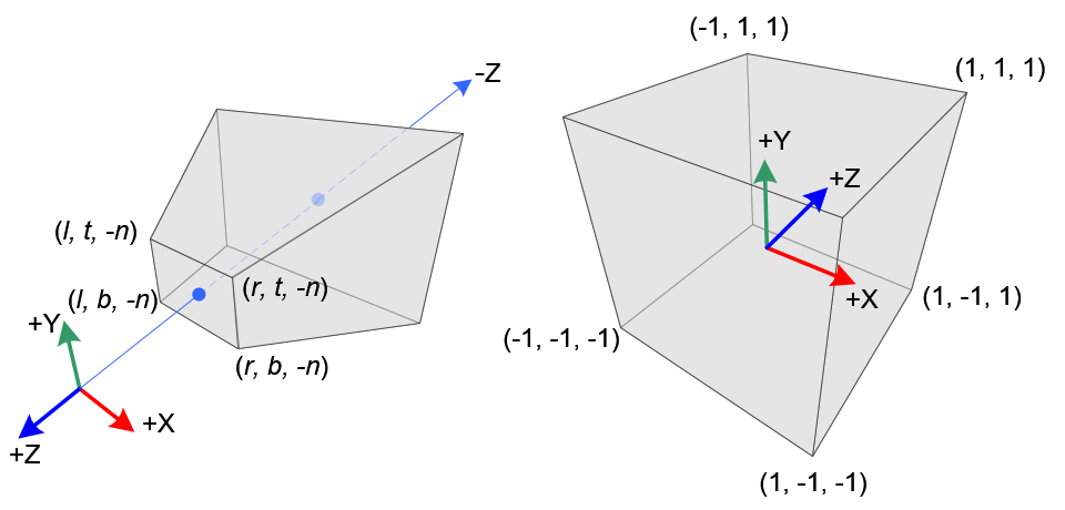
投影变换 GL_PROJECTION 是把 相机空间 下的点 (xₑ,yₑ,zₑ) 变换到 屏幕空间 的 clip 坐标 (xc,yc,zc,wc):
|
|
-
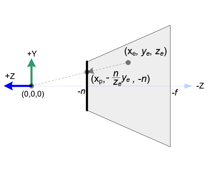
先透视投影 (1/Z缩放) 到相机的 near plane (焦距为-n)。
透视除法需要除以 -zₑ,所以齐次坐标的 wₑ = -zₑ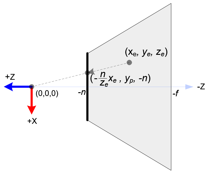
-
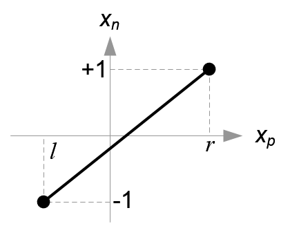
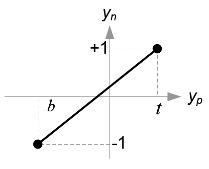
再把 x,y 的取值范围:[top,bottom],[left,right] 线性变换到[-1,1]。
-
令相机空间下的 [near, far] 的 NDC 坐标等于 [-1, 1]
-
因为是从三维到三维,要想用矩阵表达透视缩放和平移,就需要使用齐次坐标。
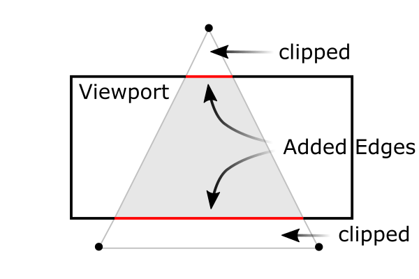
clip 坐标是 NDC 的齐次形式,所以这个矩阵(Projection Matrix) 完成了 frustum culling 和 NDC 变换。
$$ \begin{bmatrix} \frac{2}{r-l}⋅n & 0 & \frac{r+l}{r-l} & 0 \\ 0 & \frac{2}{t-b}⋅n & \frac{t+b}{t-b} & 0 \\ 0 & 0 & -\frac{f+n}{f-n} & -\frac{2fn}{f-n} \\ 0 & 0 & -1 & 0 \end{bmatrix} \begin{bmatrix} xₑ \\ yₑ \\ zₑ \\ 1 \end{bmatrix} = \begin{bmatrix} \frac{2}{r-l}⋅nxₑ + \frac{r+l}{r-l}⋅zₑ \\ \frac{2}{t-b}⋅nyₑ + \frac{t+b}{t-b}⋅zₑ \\ -\frac{f+n}{f-n}⋅zₑ -\frac{2fn}{f-n} \\ -zₑ \end{bmatrix} = \begin{bmatrix} \frac{2}{r-l}⋅n\frac{xₑ}{-zₑ} + \frac{r+l}{r-l} \\ \frac{2}{t-b}⋅n\frac{yₑ}{-zₑ} + \frac{t+b}{t-b} \\ \frac{f+n}{f-n} +\frac{2fn}{(f-n)zₑ} \ 1 \end{bmatrix} $$
NDC 空间
-
屏幕显示的世界深度范围是 near,far 两个焦平面之间的区域。 openGL 中两焦平面间的 z interval 被映射到 [-1,1],即 Normalized Device Coordinates, 变换到 NDC 后就可以根据
z_ndc把超出范围外的物体裁剪掉。屏幕窗口显示的是近焦平面。可以用 fov 控制近焦平面的边长,可以把屏幕的 t,b,l,r 映射到近焦平面的边长 [-1,1],这样屏幕显示的空间就是一个立方体。 探秘三维透视投影-齐次坐标的妙用 -奇乐bili
-
(2023-11-30) NDC = Perspective projection to the near plane with depths kept + Scaling.
相机变换矩阵
-
(不同基底间的) 坐标转换公式: 𝐯=𝐐 𝐯’=𝐑 𝐯’’ ⇒ 𝐯’’= 𝐑⁻¹𝐐 𝐯’,其中𝐐,𝐑 是不同的正交矩阵,代表坐标系,因为正交矩阵的逆等于转置,所以可以写为:𝐯’’= 𝐑ᵀ𝐐 𝐯'
-
UVN相机模型用向量定义相机朝向:N 是相机观察方向的反方向,U 由辅助向量up与N叉乘确定,辅助向量用于让相机产生偏转(不歪头一般取(0,1,0));V=N×U,V 落在 up 与 N 形成的平面上。
例如nerf的函数viewmatrix() 用于构建平均相机位姿poses_avg的UVN相机坐标系 [X|Y|Z](世界系只有一个,而相机系有多个,取平均相机系作为’新世界系’)。 -
View transformation: 把物体坐标从世界系变换到相机系下,也就是做一次相机运动的逆变换。变换过程:初始时相机系与世界系重合,(在世界系下)相机做旋转、再平移接近物体,然后相机与物体一起做逆平移、逆旋转,相机又回到初始位置,物体就变到了相机系下。
逆平移易求(取反),逆旋转不易求(求逆的顺序);但是做完逆平移后,相机系与世界系的原点重合了,只是基底不同,利用坐标转换公式就可以求出在相机系下的坐标 𝐯’’= 𝐑ᵀ𝐐 𝐯’,其中𝐑是UVN系统,𝐐 是世界系(对角阵),𝐯’是逆平移后的向量𝐓⁻¹𝐯,故最终的坐标变换矩阵(w2c外参矩阵Extrinsic matrix):𝐑ᵀ𝐐 𝐓⁻¹ -
doubt: 旋转矩阵求逆 DDG
3个矩阵
-
外参矩阵把点的 world space 坐标 Xw 变换到相机系下:Xc=R⋅Xw+T;
-
内参矩阵把点的 camera space 坐标 Xc 变换到焦平面(原点在图片中央) (加上缩放因子fx,fy和光心坐标(cx,cy)可以变换到像素坐标系u,v, 原点在图片左上角,v轴朝下)上:P=K⋅Xc;
-
相机投影矩阵 Camera projection matrix:把世界点直接变换到图像平面上(内参矩阵K₃ₓ₃ ∗ 外参矩阵[R T]₃ₓ₄ = P₃ₓ₄)。
Ref:
- 11.1 Camera matrix-CMU
- SLAM入门之视觉里程计(2):相机模型(内参数,外参数)
- Camera Calibration and 3D Reconstruction-openCV
UVN 模型
-
从外参矩阵Extrinsic matrix₄ₓ₄ 提取出相机的位置和朝向: (最后一行是齐次坐标)
最后一列是世界系中心在相机系中的位置, 左上3x3是相机在世界系下旋转运动R的转置(列向量是世界系,行向量是相机系)。如果再知道相机的观察方向,借助一个辅助向量up,就能确定UVN系统。 StackExchange -
doubt: UVN 相机模型 Google Search
(2024-04-02)
- Establishing w2c from camera position and looking-at vector.
Placing a Camera: the LookAt Function - Scratchapixel
-
The “forward” direction is defined as
From - To, because He marked the “out” of the screen as “forward” -
After determining the “forward” vector, specify a temporary “up” vector (usually (0,1,0)), which is not necessary to be perpendicular to the “forward”, to produce the “right” vector, accroding to “forward"× temporary “up”.
Once the “right” vector is obtained, re-construct the accurate “up” vector by “forward” cross “right”. Note: He define the Backward as “forward”.
-
The c2w in this post is row-major format. So, he writes each row is a direction.
-
z = -1 is the camera-space coordinate of the ray direction vector.
-
The limitation of the looking-at method is the case that the “forward” direction is aligned with the temporary “up” (0,1,0), as the cross product of 2 parallel vectors is zero $\vec{0}$. 10.4: The Cross Product - Mathematics LibreTexts
A solution is using quaternion.
-
(2024-04-04)
- NeRF builds RUB matrix (i.e., averaged c2w):average up × back (z-axis) = right (x-axis) Code
Cam Coords System
(2024-03-21)
-
确定了相机坐标系与世界坐标系的相对关系,才能正确地把一个 3D 点的世界坐标变成相机坐标系下的坐标。
假定世界坐标系是右手坐标系,相机坐标系可能不与世界系重合。
相机坐标系有 3 个轴:左(右),上(下),前(后),方向不同则:点在该方向上的坐标相差 1 个负号。而且 3 个轴的排列次序也不统一。
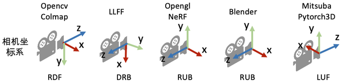
NeRF代码解读-相机参数与坐标系变换 - 陈冠英 - 知乎
- Open3D’s camera coord. sys. is RDF. camera coordinate system of visualization #1347
-
确定了相机在 世界 坐标系中的朝向和位置: Up vector, viewing direction and position, 才可以操纵相机 (Camera Manipulation):Changing roll, yaw, pitch, dollying (Slides - Hong Qin). An interactive example in LearnWebGL。 Songho also explain camera manipulation OpenGL Camera.
所以坐标变换的顺序是:世界系下的坐标 ➡ 相机系下的坐标 ➡ 相机做 6 DoF 运动(等价于物体的相机系坐标做 inverse 运动)➡ 在相机运动完成后,再把 3D 点在相机系下的坐标投影到相机平面。
-
对于矩阵 w2c,前 3 列的每一列是世界坐标系的每个 axis 在相机坐标系下的坐标。
(2024-03-25)
-
w2c 是把一个 点 的世界坐标转换成相机坐标。一个 3D 点的坐标等于 一个数组乘以坐标系。 所以 w2c 等于 rotation matrix 乘以世界坐标系:
$$ \begin{bmatrix} c_{x_1} & c_{y_1} & c_{z_1} \\ c_{x_2} & c_{y_2} & c_{z_2} \\ c_{x_3} & c_{y_3} & c_{z_3} \end{bmatrix} = \begin{bmatrix} r₁₁ & r₁₂ & r₁₃ \\ r₂₁ & r₂₂ & r₂₃ \\ r₃₁ & r₃₂ & r₃₃ \end{bmatrix} \begin{bmatrix} 1 & 0 & 0 \\ 0 & 1 & 0 \\ 0 & 0 & 1 \end{bmatrix} $$
-
因为 rotation matrix 的特性,它的一行就是目标坐标系的一个轴在 源系下的坐标。它的一列就是源系的一个轴在目标系下的坐标。
-
Each row in rotation matrix for w2c is an axis of target camera coordinate system. This can be verified by the example below:
Plotting script: Test_rotation_matrix.ipynb
同样,对于矩阵 c2w,前 3 列的每 一列 是相机坐标系的每个 axis 在世界坐标系下的坐标。 所以要 调换 相机坐标系在世界坐标系下的朝向,对 c2w 的 rot 的 某一列 乘上一个负号即可。
相机坐标系的定义影响的是 3D 点在相机坐标系下的坐标,改变相机朝向,最终体现在 3D 点在相机系下的坐标的正负。 具体来说,对于 w2c 中的旋转矩阵,要 调换 相机系的一个轴的方向,应对 rotation matrix 中对应的 一行 添加负号。
因为 NeRF 使用的是 c2w,它的旋转矩阵的 每一列 是一个相机系的轴,而且次序是 DRB 所以代码中交换第 0 列(Down) 和第 1 列 (Right),然后对 y 方向乘上 -1 变成 Up。最终变到了 OpenGL 的 RUB。 Code
-
(2024-03-24)
-
“The view matrix transforms all world coordinates to camera-space coordinates.” – LearnOpenGL - Camera
Therefore, the view matrix (extrinsics) transforms the X,Y,Z axes of the world coordinates system to X,Y,Z axes of the camera coordinates system.
Let the world X-Y-Z axes be the 3 unit column vectors, as shown in the below right matrix, they’re transformed to camera axes by a w2c:
$$ \begin{bmatrix} r₁₁ & r₁₂ & r₁₃ & t₁ \\ r₂₁ & r₂₂ & r₂₃ & t₂ \\ r₃₁ & r₃₂ & r₃₃ & t₃ \\ 0 & 0 & 0 & 1 \end{bmatrix} \begin{bmatrix} 1 & 0 & 0 \\ 0 & 1 & 0 \\ 0 & 0 & 1 \\ 1 & 1 & 1 \end{bmatrix} $$
- The extrinsics matrix transforms a world coordinates into camera-space coordinates. Next, the point will be applied with the projection matrix (scaling axes to preserve points whose $z_{clip}$ is larger than its $x_{clip},\ y_{clip},\ z_{clip}$, and performing intrinsics) for frustum clipping. The projection matrix requires a 4D homogeneous coordinates: $[x_{cam},y_{cam},z_{cam},1]^T$. So, the above extrinsic matrix has a 4-th row, that results in an additional $1$, which is reserved for storing the depth z value, for the final perspective division.
After multiplied with the extrinsics (w2c), the X,Y,Z axes of the world system are still 3 columns, but values become their coordinates under the camera coordinate system. And the 3 rows in the R of w2c are the camera coordinate system.
However, the camera coordinate system has many different matrix formats in different 3D applications. For example, OpenGL (Blender) uses RUB order.
Usually, the world space is RUB as well. So, transforming world-space coordinates to OpenGL camera-space coordiantes doesn’t need to reverse axes.
Whereas, OpenCV uses RDF camera coord. sys. Thus, the sign of y and z coordinates require flips in the camera space.
-
One of the differences between OpenCV and OpenGL is that in OpenGL, the z-axis has near and far boundary. Refer to Amy Tabb.
That post was found with searching “Converting camera poses from OpenCV to OpenGL can be easy” (DDG), that is a medium blog, which is found when searching “camera coordinates right front up” (DDG)
(2024-03-25)
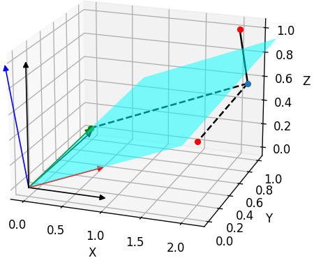
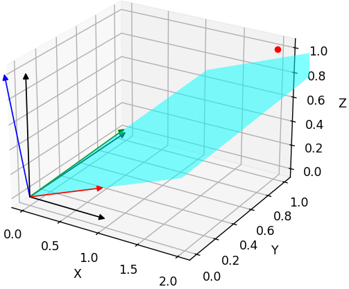
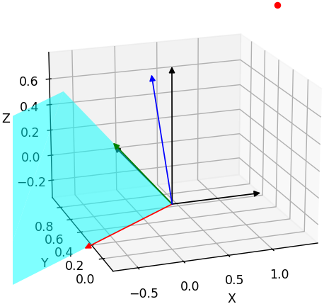
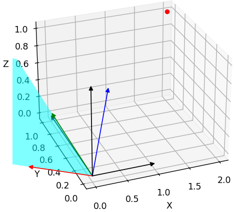
Example with a 3D point p:
-
The above figure shows the right-hand world coordinate system (X-Y-Z) and a OpenCV camera coordinate system (Right-Down-Forward).
Those 2 coordinate systems have a common origin $O$. And the camera has no rotation.
The coordinates of a point p under the world space is $(2, 2, 1)$. However, the coordinates in the camera space is $(2, -2, -1)$.
This shows that when converting the world-space coordinate to OpenCV camera-space coordinates, there is a “sign matrix”:
$$ \begin{bmatrix} 1 & 0 & 0 \\ 0 & -1 & 0 \\ 0 & 0 & -1 \end{bmatrix} \begin{bmatrix} 2 \\ 2 \\ 1 \end{bmatrix} $$
When the camera shifts from the world origin by rotation and translation, i.e., the extrinsics matrix, which transforms the axes of world system. So, the result coordinates is measured in a transformed world coordinate system.
Thus, the “sign matrix” is required to convert the “transformed world” system to OpenCV (or other) camera coordinate system.
$$ \begin{bmatrix} x_{cam} \\ y_{cam} \\ z_{cam} \\ 1 \end{bmatrix} = \begin{bmatrix} 1 & 0 & 0 & 0 \\ 0 & -1 & 0 & 0 \\ 0 & 0 & -1 & 0 \\ 0 & 0 & 0 & 1 \end{bmatrix} \begin{bmatrix} r₁₁ & r₁₂ & r₁₃ & t₁ \\ r₂₁ & r₂₂ & r₂₃ & t₂ \\ r₃₁ & r₃₂ & r₃₃ & t₃ \\ 0 & 0 & 0 & 1 \end{bmatrix} \begin{bmatrix} x_{world} \\ y_{world} \\ z_{world} \\ 1 \end{bmatrix} $$
Therefore, the matrix transforming world coordinates to OpenCV camera coordiantes is:
$$ \begin{bmatrix} r₁₁ & r₁₂ & r₁₃ & t₁ \\ -r₂₁ & -r₂₂ & -r₂₃ & -t₂ \\ -r₃₁ & -r₃₂ & -r₃₃ & -t₃ \\ 0 & 0 & 0 & 1 \end{bmatrix} $$
-
Since w2c transforms world axes to camera-space coordinates, the coordinates performed by w2c must be a world coordinates of a point, instead of a camera coordinates.
So, the “sign matrix” must be applied after w2c. Otherwise, the world coordinate becomes a camera coordinate immediately, which doesn’t match w2c. Specifically, the below order is incorrect:
$$ w2c \begin{bmatrix} 1 & 0 & 0 & 0 \\ 0 & -1 & 0 & 0 \\ 0 & 0 & -1 & 0 \\ 0 & 0 & 0 & 1 \end{bmatrix} \begin{bmatrix} x_{world} \\ y_{world} \\ z_{world} \\ 1 \end{bmatrix} $$
In other words, the “sign matrix” should be applied on a camera-space coordinates.
-
In NeRF, the provided matrix is c2w, where each column of the rot is a camera axis, and the columns order is DRB. So, the first 2 columns need to switch, thus, becoming RDB. Then, to align the camera coordinate system of Blender: RUB, the second row (the U axis) needs to be multiplied with -1. Code
(2024-03-26)
-
Note: the rotation matrix in
c2wandw2care different. For the rot inc2w, each column is an axis of camera, so reversing the direction of a camera axis requires multiplying a column with -1.Whereas, for the rot in
w2c, each row is an axis of a camera. Thus, to reverse a camera axis, a row needs to be negated.
-
(2024-03-26)
Test reversing a row and a column in a rotation matrix for w2c:
| Original Rot in w2c | Flip 0th row | Flip 0th column |
|---|---|---|
|
|
|
| $$\begin{bmatrix} 0.970 & 0.00747 & 0.241 \\ -0.0147 & 0.999 & 0.028 \\ -0.241 & -0.0309 & 0.969 \end{bmatrix}$$ | $$\begin{bmatrix} -0.970 & -0.00747 & -0.241 \\ -0.0147 & 0.999 & 0.0282 \\ -0.241 & -0.0309 & 0.969 \end{bmatrix}$$ | $$\begin{bmatrix} -0.970 & 0.00747 & 0.241 \\ 0.0147 & 0.999 & 0.0282 \\ 0.241 & -0.0309 & 0.969 \end{bmatrix}$$ |
| $p_{cam}=[2.18994, 0.99823, 0.45571]$ | $p_{cam}=[-2.18994, 0.99823, 0.45571]$ | $p_{cam}=[-1.69110, 1.05720, 1.42213]$ |
-
A row of the rotation matrix in w2c is the coordinates of a camera axis in the world space.
-
A column is the coordinates of a world axis in the camera space.
-
The original rotation matrix transforms the world axes to a tilted coordinate system.
-
Flip the 0th row of the rotation matrix: only the X axis entirely turns to the oppsite direction.
-
Flip the 0th row of the rotation matrix: the x component of all the X-Y-Z axes are affected. Apparently, this is not desired result. When flipping a single axis, the other axes should be unchanged.
Figure plotting script: Test_reverse_cam_axis.ipynb
Identify Cam Axes
只有旋转矩阵 R,但不知道相机在世界坐标系中的朝向(也不知道各轴的次序)。
- @will 在 23-11-10 8:25 AM 说:画出来看看正不正对场景。
- @什么办 在 22-11-21 8:50 PM 展示过他用 plt 画的相机位姿。
(2024-03-27)
-
The pose1 does not face towards the object (MVSNet_testing/dtu/scan1/cams/00000000_cam.txt):
R for w2c rect_001_0 (full) mod signs 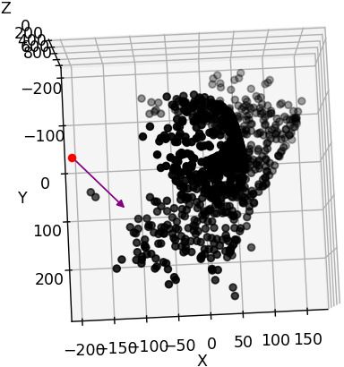

-
I have dragged the figure to make the z axis upside down. The camera position is $[-191.02, 3.28832, 22.5401 ]$ And I feel the pose should be $[3, 191, 22]$
(2024-03-30) Camera position was wrong, but it’s not due to signs. The 4-th column in w2c is not the camera position in world.
-
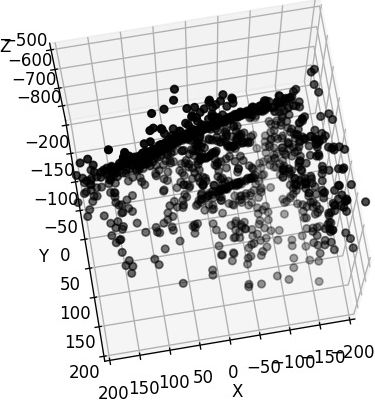
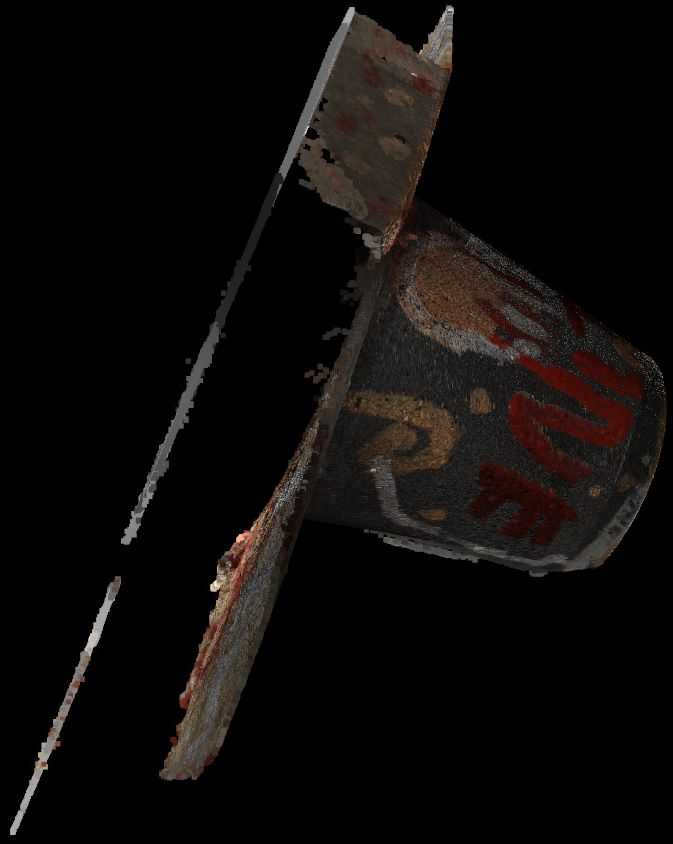
Dragging z-axis to upside down is equivalent to negating the z coordinate and switching the x and y of points coordinates. Specifically, given a point (x,y,z), dragging z to flip equals:
x=y; y=x; z=-zDrag manually Flip z and switch x,y 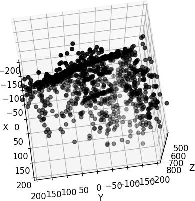
Code for modifying axes for scan23
1 2 3 4 5 6 7 8 9 10 11 12 13 14%matplotlib widget import numpy as np import matplotlib.pyplot as plt import open3d as o3d pcd = o3d.io.read_point_cloud("/mnt/data2_z/SampleSet/MVS Data/Points/stl/stl023_total.ply", format='ply') vs = np.asarray(pcd.points) samples = vs[np.random.choice(vs.shape[0],1000)] x = samples[:,1] y = samples[:,0] z = -samples[:,2] fig = plt.figure() ax = fig.add_subplot(111, projection='3d') ax.scatter(x, y, z, color='black')
-
(204-03-28)
- I know DTU matches the setup of OpenCV because the function
cv2.decomposeProjectionMatrixis used. But, I’m still confused about the scene visualization with matplotlib.
(2024-03-30)
-
The 4-th column of the w2c is not the camera center position in world space!! The camera position in world should be the 4-th column of c2w, i.e., $-R_{w2c}^T t_{w2c}$.
And the
treturned bydecomposeProjectionMatrixis the camera position as well. -
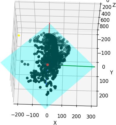
After correcting the camera center position, the camera geometry is correct:
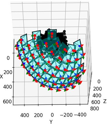
Plotting script: gist
-
Identifying the axes directions should be independent of camera geometry.
Only drawing one camera may not easily indicate if it’s facing the scene.
(2024-03-31)
-
Open3D can set the window (visualizer) to be the specified camera pose.
-
Change
set_frontto different row in the rotation mat:Code
 1
 2
 3
 4
 5
 6
 7
 8
 9
10
11
12
13
14
15
w2c = np.array([[0.970263, 0.00747983, 0.241939, -191.02], [-0.0147429, 0.999493, 0.0282234, 3.28832], [-0.241605, -0.030951, 0.969881, 22.5401], [0.0, 0.0, 0.0, 1.0] ]) pcd = o3d.io.read_point_cloud("/home/yi/Downloads/DTU_SampleSet/MVS Data/Points/stl/stl001_total.ply", format='ply') vis = o3d.visualization.VisualizerWithKeyCallback() vis.create_window() vis.get_render_option().background_color = np.asarray([0, 0, 0]) view_ctl = vis.get_view_control() vis.add_geometry(pcd) view_ctl.set_front(w2c[0][:3]) vis.run() vis.destroy_window()set_front(w2c[2][:3]) set_front(w2c[0][:3]) 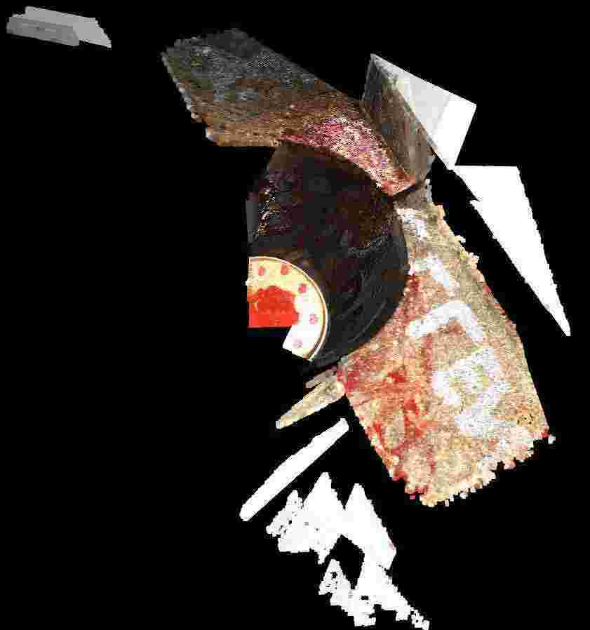
-
Set the extrinsic to simulate a camera pose: Determining the Proper Camera Position #2338
Code
 1
 2
 3
 4
 5
 6
 7
 8
 9
10
11
12
13
14
15
16
17
18
19
20
21
22
23
import open3d as o3d import numpy as np pcd = o3d.io.read_point_cloud("/home/yi/Downloads/DTU_SampleSet/MVS Data/Points/stl/stl001_total.ply", format='ply') vis = o3d.visualization.VisualizerWithKeyCallback() vis.create_window() vis.get_render_option().background_color = np.asarray([0, 0, 0]) vis.add_geometry(pcd) view_ctl = vis.get_view_control() w2c = np.array([[0.970263, 0.00747983, 0.241939, -191.02], [-0.0147429, 0.999493, 0.0282234, 3.28832], [-0.241605, -0.030951, 0.969881, 22.5401], [0.0, 0.0, 0.0, 1.0] ]) cam = view_ctl.convert_to_pinhole_camera_parameters() cam.extrinsic = w2c view_ctl.convert_from_pinhole_camera_parameters(cam, True) current_param = view_ctl.convert_to_pinhole_camera_parameters() print(current_param.extrinsic) vis.run() vis.destroy_window()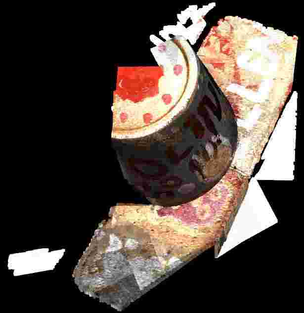
-
The argument
allow_arbitrary=Trueis required (using 0.18.0), reminded by: How to you position camera and look at certain location in Open3D? #1483This argument is added to free the limitation on pinhole camera models. ConvertFromPinholeCameraParameters() failed #834
Similar issues:
-
-
-
“view matrix” means w2c. While “world transformation matrix” is c2w. 3D GEP
-
Each column in c2w is a camera axis coordinates in world space. So, 3 columns represent directions, such as RDF, and the 4-th colmun is the camera center in world space.
-
He gave a code demo to show the matrix format in column-major memory accessing.
-
OpenCV2OpenGL
(2024-03-29)
-
Just negate the 2nd and 3rd rows in the rotation matrix that transforms word coords to cam coords. Such that, RDF camera system becomes RUB. (And note OpenGL reads matrix by columns.) OpenCV to OpenGL coordinate system transform - SO

This process can be done with a “sign matrix”: $[[1,0,0,0],\ [0,-1,0,0],\ [0,0,-1,0],\ [0,0,0,1]]$.
(2024-04-02)
-
Mapping a coordinate system to another has two transformations: rotation+translation [R|t] and sign matrix.
Converting camera poses from OpenCV to OpenGL can be easy - readmedium (Found when searching “opencv to opengl transformation” DDG)Specifically, change the source basis first, and then flip axes of the source basis (world) to target basis (camera).
-
I realized that the terminologies: w2c and c2w are siutable for the transition between world and the OpenGL camera coordinate syste, beacuse their axes are aligned, i.e., both RUB.
Otherwise, for example, between world and OpenCV camera system, the world system is not directly becoming the target camera system after rotation and translation [R|t].
-
That post also takes the column-major memory access into account.
-
DTU dataset
Original
(2024-02-21)
DTU Homepage Each object scan is taken from 49 fixed camera positions.
For the SampleSet, the images dimensions are 1600x1200:
|
|
The camera projection matrix 𝐏₃ₓ₄ from world to image, i.e. K@[R|t] (Casmvsnet and SO):
|
|
-
(2024-03-27) The P is estimated by Matlab, and Matlab regards camera coordinates system as RDF (mentioned in Multi-cameras on same coordinate system - Dima found by Perplexity), which is the same as OpenCV camera model.
The P can be decomposed to K,R,t by decomposeProjectionMatrix():
|
|
The original intrinsic matrix K (performed K/K[2][2]) is:
|
|
-
It’s aligned with the intrinsics in mvs_training (not the cams in
train/folder):mvs_training/dtu/Cameras/00000000_cam.txt
1 2 3 4 5 6 7 8 9 10 11 12 13z@homepc:~/Downloads/Datasets_life/mvs_training/dtu/Cameras$ cat 00000000_cam.txt extrinsic 0.970263 0.00747983 0.241939 -191.02 -0.0147429 0.999493 0.0282234 3.28832 -0.241605 -0.030951 0.969881 22.5401 0.0 0.0 0.0 1.0 intrinsic 2892.33 0 823.205 0 2883.18 619.071 0 0 1 425 2.5
The table lists focal length and image resolution correspondence:
| Scale | resolusion | cropped | f_x |
|---|---|---|---|
| 1 | 1200x1600 | 2892.3 | |
| 1/2 | 600x800 | 512x640 | 1446.1 |
| 1/4 | 300x400 | 723.08 | |
| 1/8 | 150x200 | 361.5 |
(2024-03-27)
-
In Dima’s answer, he described RDF as the world space. That means the extrinsics has been applied by the “sign matrix”, which changes the world axes to camera axes. So, the R decomposed from P essentially corresponds to the RDF coordinates system.
In other words, the camera coordinate system is used as the world coord. sys.
Whereas, the world system during visualization is usually RUB (Y-axis is Up), like OpenGL. So, the object is upside down when plotting the point cloud with matplotlib.
And the ccs in Open3D also is RDF (relative to world space RUB), so its initial w2c has reverse the y-axis and z-axis of the world space:
1 2 3 4[[ 1. 0. 0. -0.] [-0. -1. -0. 0.] [-0. -0. -1. 0.] [ 0. 0. 0. 1.]]Code: Print current cam pose
1 2 3 4 5 6 7 8import open3d as o3d vis = o3d.visualization.VisualizerWithKeyCallback() vis.create_window() view_ctl = vis.get_view_control() current_param = view_ctl.convert_to_pinhole_camera_parameters() print(current_param.extrinsic) vis.run() vis.destroy_window()
MVSNet
(2024-02-22)
-
Training set: dtu_training.rar (19G) (“mvs_training/dtu/”)
As mentioned in the section 4.1 of the MVSNet paper, the training images are 1/2 * (1200,1600) = (600,800), which then cropped to (512,640).
In addition, because the camera is looking at feature maps, the focal lengths should be scaled with the ratio of the size of feature map to the input image size.
As feature map size (128,160) is 1/4 input image (512,640) mentioned in paper section 3.1, the focal_x should be: 2892.33 * 1/2 * 1/4 = 361.541. Issue
Note: The already calculated trianing camera params are placed in “mvs_training/dtu/Cameras/train”. Code While the cameras displayed outside the “train/” are params corresponding to the original DTU images (1200,1600).
1 2 3 4 5 6 7 8 9 10 11 12 13 14 15 16z@lambda:~/Downloads/mvs_training/dtu$ identify Rectified/scan1_train/rect_001_0_r5000.png Rectified/scan1_train/rect_001_0_r5000.png PNG 640x512 640x512+0+0 8-bit sRGB 626KB 0.000u 0:00.000 z@lambda:~/Downloads/mvs_training/dtu$ cat Cameras/train/00000000_cam.txt extrinsic 0.970263 0.00747983 0.241939 -191.02 -0.0147429 0.999493 0.0282234 3.28832 -0.241605 -0.030951 0.969881 22.5401 0.0 0.0 0.0 1.0 intrinsic 361.54125 0.0 82.900625 0.0 360.3975 66.383875 0.0 0.0 1.0 425.0 2.5 -
Testing set (dtu.zip) has the full-size images:
Testing images are’t downsized twice or cropped, so the focal lengths only times 1/4. Code
1 2 3 4 5 6 7 8 9 10 11 12 13 14 15 16z@lambda:~/Downloads/data2/MVSNet_testing/dtu$ identify scan1/images/00000000.jpg scan1/images/00000000.jpg JPEG 1600x1200 1600x1200+0+0 8-bit sRGB 705KB 0.000u 0:00.000 z@lambda:~/Downloads/data2/MVSNet_testing/dtu$ cat scan1/cams/00000000_cam.txt extrinsic 0.970263 0.00747983 0.241939 -191.02 -0.0147429 0.999493 0.0282234 3.28832 -0.241605 -0.030951 0.969881 22.5401 0.0 0.0 0.0 1.0 intrinsic 2892.33 0 823.205 0 2883.18 619.071 0 0 1 425 2.5 -
The factor
adaptive_scalingis used for the requirement that image size must be evenly divisible by 32 (e.g., 864x1152) and reducing images for limited VRAM. So, this step will also change resolution, focals, and principle points: Code
MVSNet-PyTorch
PixelNeRF
(2023-08-17)
“rs_dtu_4” follows the DVR format. Each object has 6 matrices. Take the object 0 as an example:
|
|
-
Use
cv2.decomposeProjectionMatrix(P)to solve 𝐊,𝐑,𝐭 from 𝐏₃ₓ₄. Code in PixelNeRF:1 2 3 4 5 6 7 8 9 10 11 12 13 14 15 16 17 18 19 20P = all_cam["world_mat_0"] P = P[:3] # (3,4), projection: Intrinsics * Extrinsics * 3Dpoint K, R, t = cv2.decomposeProjectionMatrix(P)[:3] K = K / K[2, 2] # Not the camera_mat, # Xc = extrinsics*Xw extrinsics = np.eye(4, dtype=np.float32) extrinsics[:3,:3] = R # The 4th column is the rotated transVec extrinsics[:3,3] = -(R @ (t[:3]/t[3]))[:,0] print(extrinsics) # c2w equals inverse extrinsics c2w = np.eye(4, dtype=np.float32) c2w[:3, :3] = R.transpose() # The 4th column is the normalized t decomposed by cv2. c2w[:3, 3] = (t[:3] / t[3])[:, 0] c2w == np.linalg.inv(extrinsics)-
The
K(focal) in pixelNeRF is about twice as large as theintrinsicsof “dtu_training”, because the image size of pixelNeRF (300x400) is twice as small as MVSNet (or MVSNeRF) in each dimension, where (512x640) is cropped from (600x800). It’s like when you observe the scene from far away, the image captured gets smaller.Since the projection matrix computed from K@(R|Rt) is different, the decomposed intrinsics will be different.
-
(2024-02-22) The above statement may be wrong. Take the 1st camera as an example:
1 2 3 4cams = np.load("pixel-nerf/data/DTU_Dataset/rs_dtu_4/DTU/scan1/cameras.npz") P = cams['world_mat_0'][:3] K, R, t = cv2.decomposeProjectionMatrix(P)[:3] K / K[2, 2]The
Kequals 1/4 the intrinsics of the original DTU dataset:1 2 3[[ 7.23082629e+02, -6.20158374e-05, 2.05801318e+02], [ 0.00000000e+00, 7.20793819e+02, 1.54767729e+02], [ 0.00000000e+00, 0.00000000e+00, 1.00000000e+00]]Because camera is used to project 3D points ont feature maps, the focals should be scaled based on the ratio of the feat map to the original image (1600,1200).
-
-
c2w(3x4) is not the Inverse Projection Matrix (4x4).-
Inverse Projection Matrix =
np.linalg.inv(Projection Matrix) -
Projection matrix converts a 3D world coords to 2D pixel coords;
-
Extrinsics ( w2c = [R|t] = (R|Rt) ) converts 3D world coords to 3D camera coords.
-
Inverse Extrinsics ( c2w ) converts 3D camera coords to 3D world coords.
-
Give Extrinsics and Intrinsics (of dataset “dtu_training” from MVSNet), the Projection matrix can be restored as implemented in MVSNeRF
def build_proj_mats()
-
-
The translation vector also needs rotation. OpenCV Decompose projection matrix
-
Projection matrix = Intrinsics@Extrinsics = K@[R|t] = K@(R|Rt) = (KR|KRt)
-
Decomposed
tneeds normalization, and to be negated sometimes:1 2 3 4 5 6 7 8 9 10 11 12 13 14 15K = np.array([[631, 0, 384], [ 0, 631, 288], [ 0, 0, 1]]) R = np.array([[-0.30164902, 0.68282439, -0.66540117], [-0.63417301, 0.37743435, 0.67480953], [ 0.71192167, 0.6255351 , 0.3191761 ]]) t = np.array([ 3.75082481, -1.18089565, 1.06138781]) P = np.eye(4) P[:3, :3] = K @ R P[:3, 3] = K @ R @ t K1, R1, t1 = cv2.decomposeProjectionMatrix(P[:3, :])[:3] t == -(t1[:3]/t1[3]) -
The original
tcan be obtained directly from projection matrix:np.linalg.inv(P[:3,:3]) @ P[:3,3], i.e., use the inverse rotation to rotate the transVec back.
-
(2024-03-29)
-
The
treturned bycv2.decomposeProjectionMatrixis the position of a camera in the world space. (Docs) So, it’s actually the translation vector in c2w: $t_{c2w}$.Because
t(denoted as $t_{cv2}$ for later) is the camera center, its corresponding camera-space coordinates is 0. Thus, this is the relationship:$$t_{cv2} = R_{c2w} 0 + t_{c2w} \\ t_{cv2} = t_{c2w}$$
To get the $t_{w2c}$, i.e., the 4-th column in the w2c (extrinsics), the conversion formula is $t_{w2c} = - R_{w2c} t_{c2w}$.
This relationship can be derived from the transformation between camera-space coordinate X and world coordinate P:
$$ P = R_{c2w} X + t_{c2w} \\ X = \underbrace{R_{c2w}^T}_{R_{w2c}} P \underbrace{- R_{c2w}^T t_{c2w}}_{t_{w2c}} $$
Considering the above example,
tis not the 4-th column in extrinsics, but the-R @ (t/t[3])[:3]is.1 2 3 4 5 6 7 8 9 10 11 12 13 14>>> t array([[-0.99198397], [ 0.00603084], [-0.12611273], [-0.00519817]]) >>> t/t[3] array([[190.83346195], [ -1.16018638], [ 24.26100588], [ 1. ]]) >>> -R @ (t/t[3])[:3] array([[-191.01958721], [ 3.28830259], [ 22.54011993]])Therefore, in PixelNeRF directly used
tas the 4-th column of the c2w (named aspose)I was reminded by:
-
How to find camera position and rotation from a 4x4 matrix? - SE (surfaced by “given camera extrinsics, how to determine right, up, front” DDG)
$$0=RC+T \\ C=−R^T T$$
In the folllwing posts, they all mentioned the 4-th column in Extrinsics is not the camera center, but $-R_{c2w}^T C$, where C is the camera center in world space:
-
Dissecting the Camera Matrix, Part 2: The Extrinsic Matrix - ksimek
He derived w2c from c2w, ie. w2c = (c2w)⁻¹, and provided an interactive demo for visualizing camera intrinsic, extrinsic.
-
Camera Pose & Pose Estimation - MiaoDX refered by Camera extrinsic matrix from camera location and rotation
-
How to plot the camera and image positions from camera calibration data? - SO
The OP cited wikipedia $C = -R^{-1} T = -R^T T$
-
inv([R|t]) = [R'|-R'*t]Camera position in world coordinate from cv::solvePnP - SO
